Sailor Hat with ESP32
| Description | Documentation for the Sailor Hat with ESP32 (SH-ESP32), a powerful microcontroller development board for the marine environment |
| Author(s) | Hat Labs |
| Repository | https://github.com/hatlabs/sh-esp32 |
Introduction
Sailor Hat with ESP32 (SH-ESP32) is a powerful microcontroller development board for the marine environment.
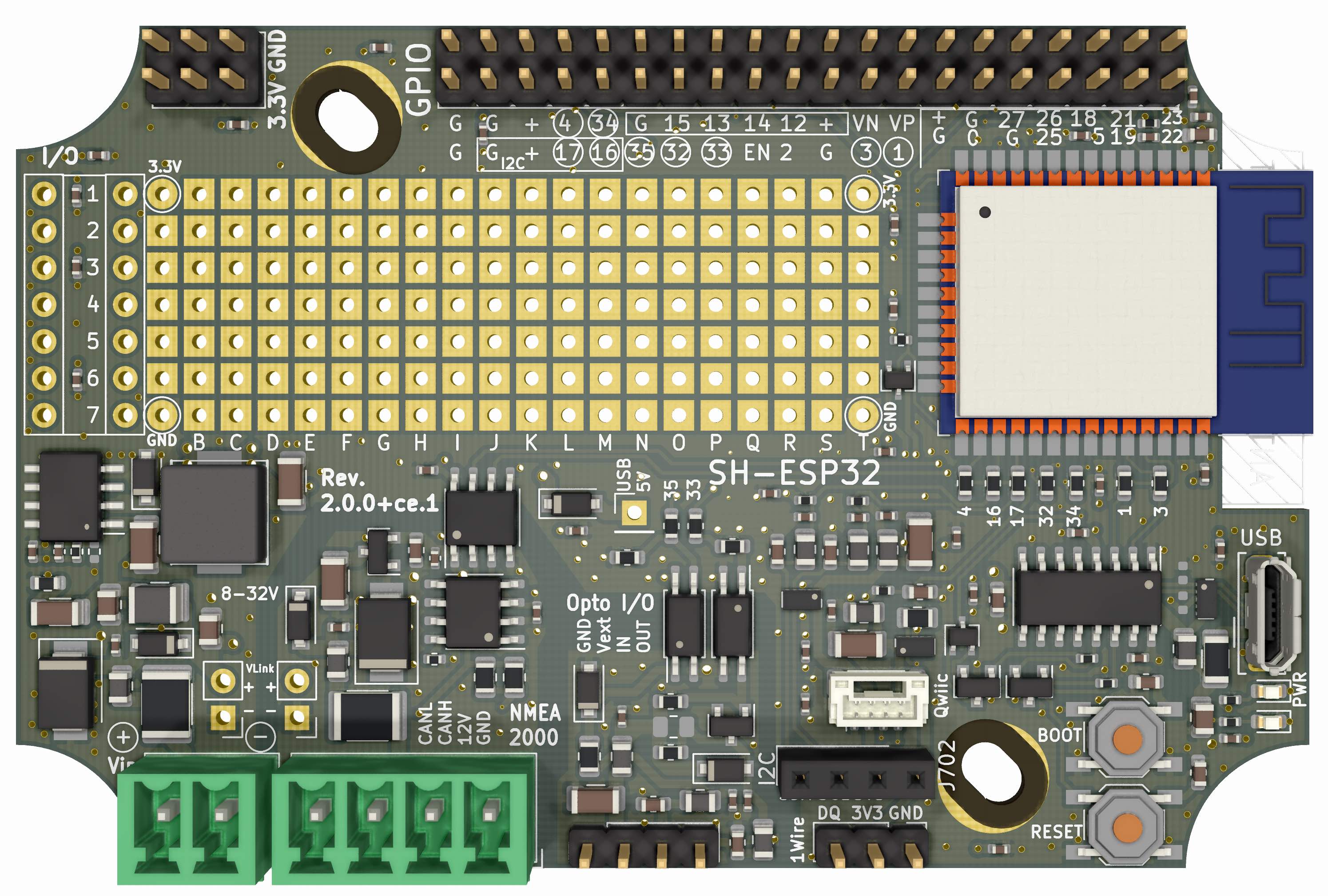
SH-ESP32 Rev. 2 top view.
With SH-ESP32 you can easily create all kinds of sensors and control interfaces for your boat. Examples include RPM or fuel and water tank level meters, bilge alarms, chain counters, electrical compasses, attitude sensors, and so on. Control interface examples include automatic engine room blower control, smart light switching, or smart fridge thermostats. It integrates easily both to Signal K as well as NMEA 2000 and can be used as a NMEA 2000 gateway device.
SH-ESP32 can be plugged directly to any 12V or 24V power system. Special emphasis has been placed on electrical compliance: the board can handle most power surges present on an automotive or marine 12V or 24V power system. Equally importantly, the inputs and outputs have protection for electrostatic discharges (static electricity), and are designed to not produce electromagnetic emissions (disturb other sensitive devices such as VHF radios or GPS antennas), and to be protected against electromagnetic interference (will not be disturbed by a VHF, SSB, or a radar).
SH-ESP32 is open hardware, licensed under the Creative Commons Attribution-ShareAlike 4.0 International license. You can create your own SH-ESP32 derivatives as long as you share them under similar terms!
Getting the hardware
Ready-made CE-certified SH-ESP32 boards can be purchased from Hat Labs Ltd. All design files are also available at the SH-ESP32 hardware GitHub repository.
NMEA 2000 compatibility
SH-ESP32 is open hardware and the provided and suggested software are open source under liberal software and hardware licenses. NMEA 2000 is a proprietary standard by National Marine Electronics Association (NMEA). The licensing and certification processes of NMEA are fundamentally incompatible with open source development, and while several references to NMEA 2000 are made in this documentation, the products of Hat Labs Ltd are not, and will not be certified by NMEA.
However, a lot of effort, both in the lab and in the real-world environment, has been put into ensuring that SH-ESP32 is electrically compatible with NMEA 2000, and that the supplied example software are compatible with NMEA 2000 communication protocol.
Getting started
Assembling the hardware
Revision 2 boards
Revision 2 boards (the ones with the green pluggable screw terminals on board) come pre-assembled, so no soldering is required. Pluggable screw terminal plugs used for power input and CAN bus interfacing are provided in the sales package together with some wire for making the connections.
Revision 1 boards
The SH-ESP32 boards sold by Hat Labs are mostly unassembled. Only the USB connector has been soldered on at delivery. You need to solder on the remaining connectors, or at least the ones you need. A set of connectors is provided in the sales package. Depending on your requirements, you may want to swap them for something else. For example, the power and CAN bus connectors can be replaced with 2.5 mm pluggable terminal blocks that permit easier disconnection of individual wires and is mechanically sturdier. Similarly, male headers may be replaced with female ones to allow plugging in devices with compatible male headers.
To assemble the connectors, a soldering iron and some solder is required. It is highly recommended to use an iron with controllable temperature. Flux can also be helpful. SH-ESP32 has ground plane on up to three of the four PCB layers. They conduct heat efficiently away from the solder joint -- to solder the connectors, use as large solder tip as you can easily work with. A good starting point for the soldering iron temperature is 320°C. If that doesn't work well, increase the temperature gradually.
To solder the connectors, place them on the board one by one and use some tape to hold them in place when you turn the PCB around for soldering. Male header pins can be pushed through the tape for even easier manipulation.
Touch both the pin and the pad with the iron tip and then feed some solder wire to the opposite side of the pin, as shown in the figures below. The whole process should ideally take only a couple of seconds, although in practice some fumbling is normal. Try avoiding heating the pins too long, though -- the plastic connector or header body will melt and the pin will become crooked. Tiny deformation is not dangerous, though, as long as it doesn't prevent you from plugging the connector to the header.
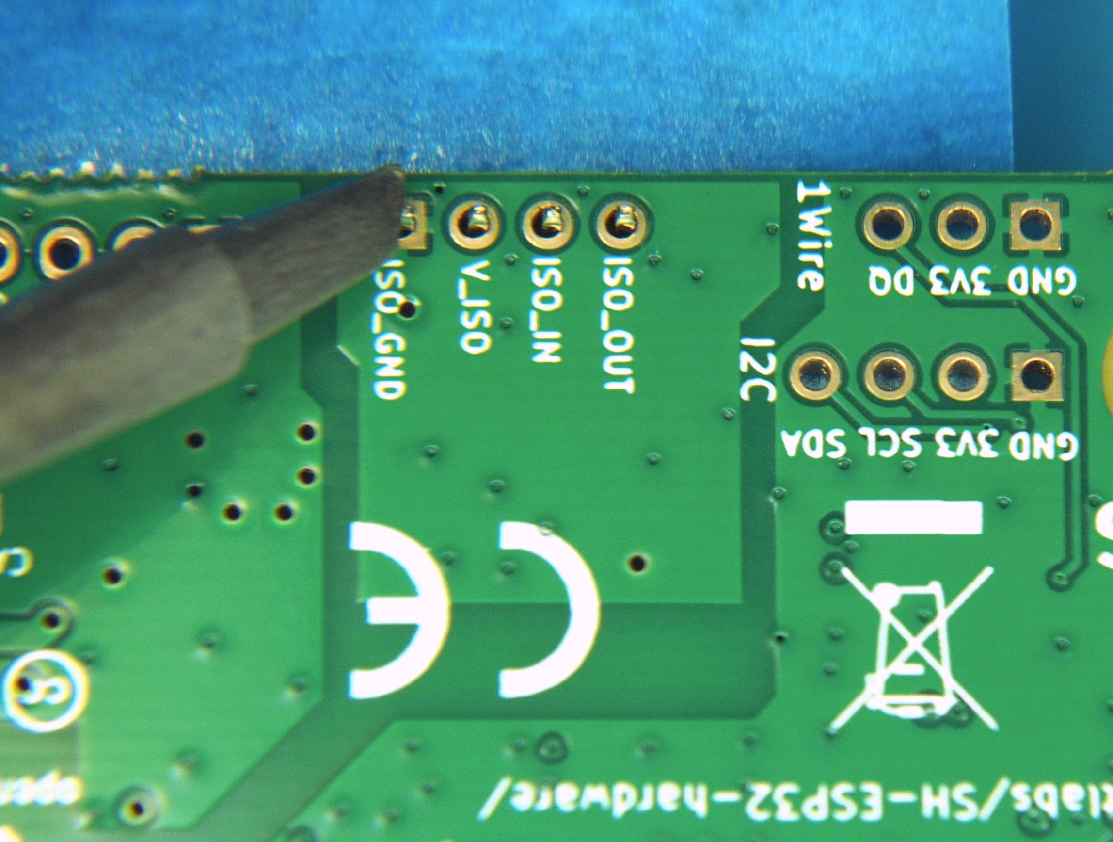
Heat the pins and the pads with the solder tip.
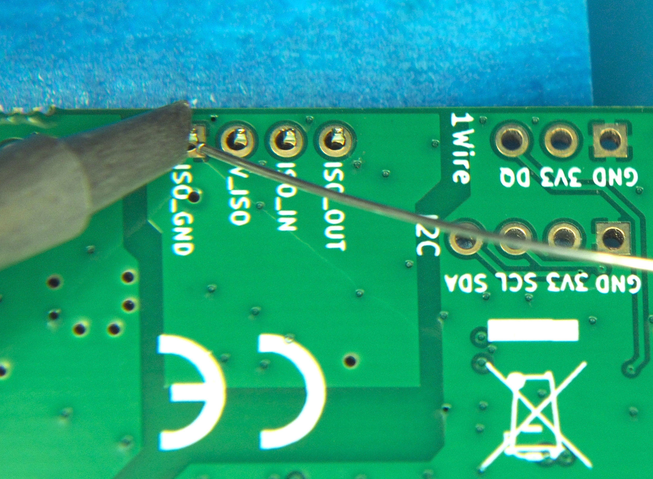
Feed solder to the pins and the pads, not the iron tip. Although, to be fair, a tiny bit of solder on the tip may help conducting heat...
A bit of solder on the iron tip is OK for helping with heat transfer, but if you add a big blob of solder onto the tip, all flux burns off and the solder becomes difficult to work with. In that case it's better to wipe the tip clean and apply some fresh solder. For stubborn pins add a generous amount of flux. It helps the solder flow more easily.
The end result should be as shown in the following figure.
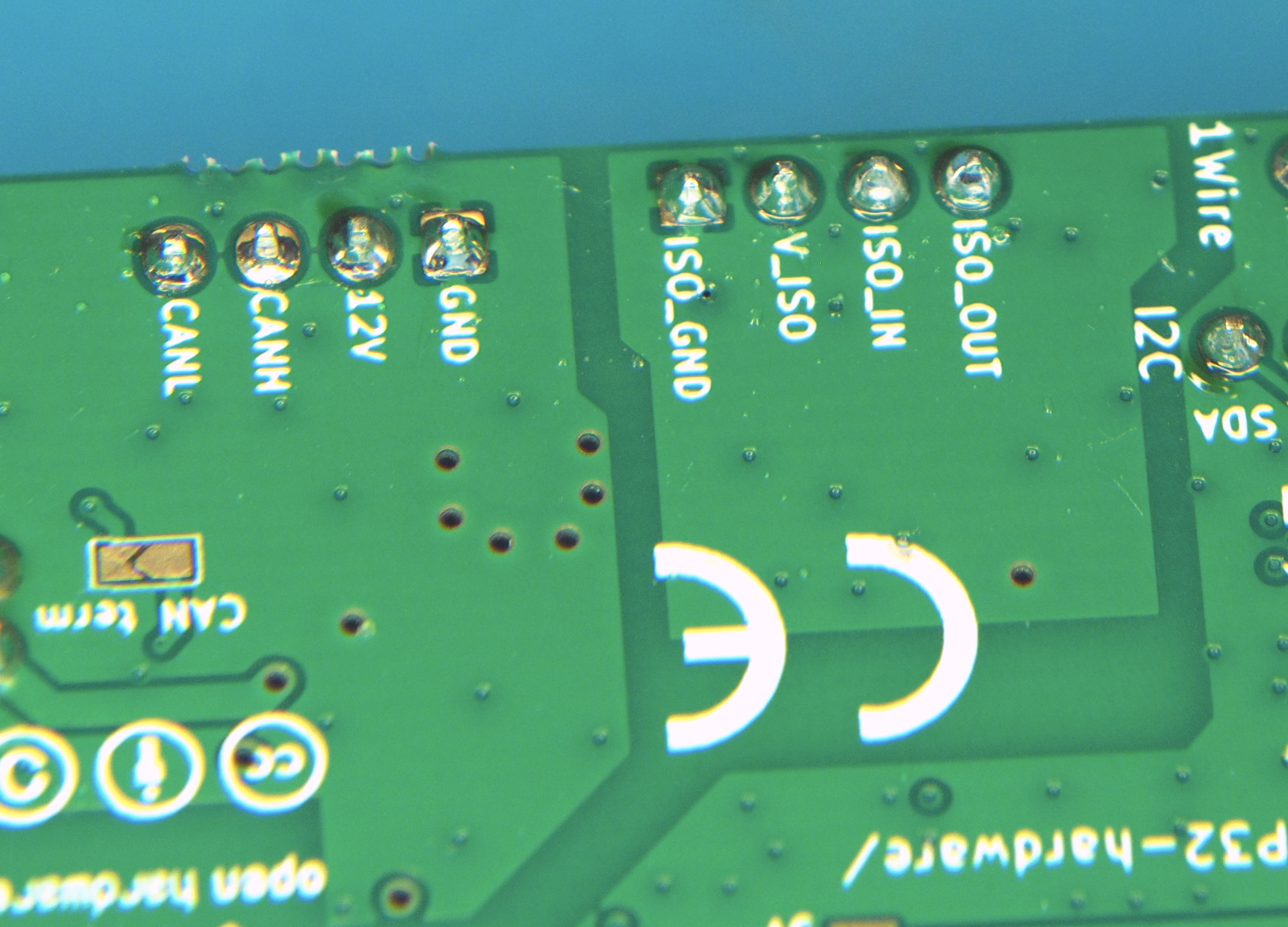
An example of well soldered pins.
Enclosures
Boats can be nasty environments for electronics; there's salt water, high humidity, and often some condensation, too. It is highly recommended to keep the SH-ESP32 in an enclosure in "production". The board has been designed to fit in a 100x68x50 mm plastic waterproof enclosure as shown in the figure below, available either at the Hat Labs web store, or at any online marketplace such as Amazon, Ebay, or AliExpress.
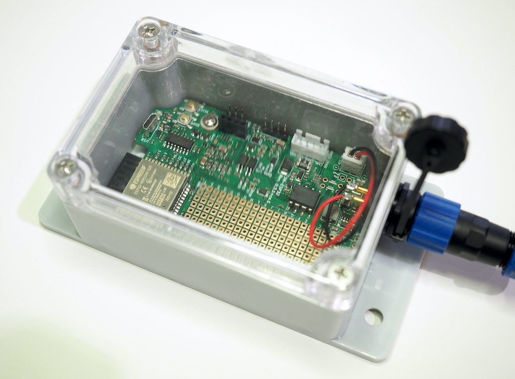
SH-ESP32 standard enclosure.
Mounting the board
There is some slight variation in the location of the plastic standoffs on generic enclosures, so you might have to get creative when mounting the board. Plastic adhesive standoffs (3 mm hole size, height 6 mm or less, available online) such as the ones shown below, allow you to mount the board easily in any kind of an enclosure.
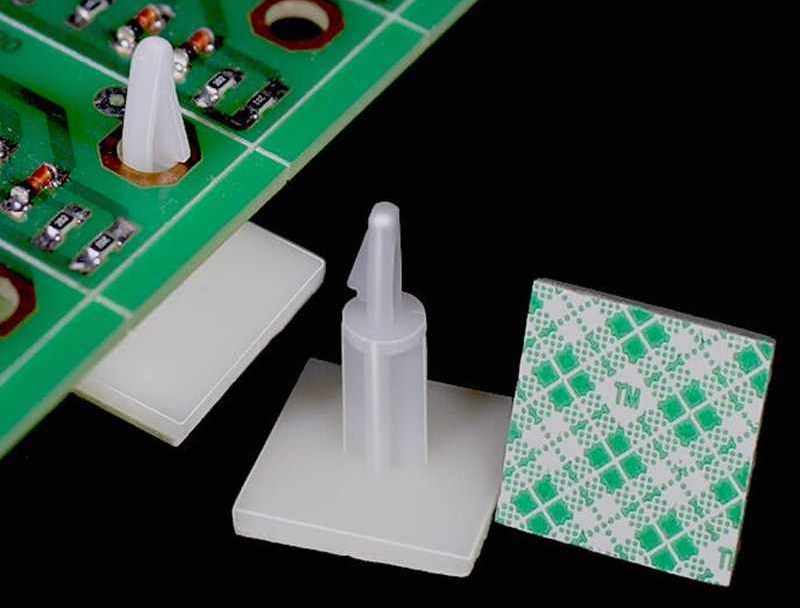
Adhesive standoffs.
Drilling holes
The enclosures don't have any pre-drilled holes for connectors or wire glands on them. At a very minimum, you need one hole for power or NMEA 2000 input. Usually you want some more, though, to connect external sensors or wiring.
To drill the holes in the thin plastic, a step drill bit (one that looks like a small metal Christmas tree), is recommended. Standard metal drill bits may easily bite too hard and crack the plastic. If you don't have a step drill bit at hand, use standard metal bits. Start with a small diameter and increase the diameter with small increments to limit the risk of cracking the case.
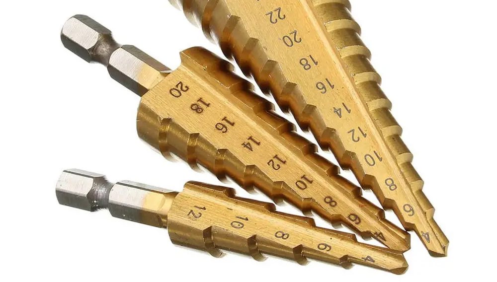
An example of step drill bits.
Plan your hole placement in advance. If you only need a couple of holes, placing them on the short side may result in the neatest outcome. If you need three or more connectors, place them on the long side or on both ends. Nothing prevents you from adding connectors on the lid, either. If there is even the slightest possibility of condensation or deck leaks or any other water drops near the planned installation location, try to have the connectors leave the enclosure downwards. This should prevent any water ingress even if the connectors weren't perfectly tight.
When placing the holes horizontally, make sure that the connector nut will clear both the enclosure corner bumps and the nut of any adjacent connector. Vertically, the connector should be as high as reasonable. This will help the connector clear any headers or components on the PCB. The hole edge could be 4-5 mm or 3/16" from the lid seam. When using PG9 cable glands, the hole might have to be even closer to the lid. Drill carefully!
Suitable hole size for different connectors:
- SMA (WiFi antenna): 6.5-7 mm or 1/4"
- PG7 cable gland and M12 (NMEA 2000) panel connector: 12 mm or 1/2"
- SP13 panel connectors (blue-black plastic connectors): 13-14 mm. 1/2" probably works with a bit of wiggling.
- PG9 cable gland: 16 mm or 5/8"
Soldering the panel connectors
When soldering the internal wires to the panel connectors, always use heat shrink tube on the individual wires. Always remember to slide the heat shrink on the wires before soldering... When soldering the panel connectors, the general guidance given in Section FIXME applies. Usually you can first add solder to the connector pin cavity and then re-melt the solder and insert the wire.
Hardware description
Note: The pictures below show a Revision 1 board. Rev. 2 boards are functionally identical but have different power and CAN connectors and minor component changes.
Tour around the board
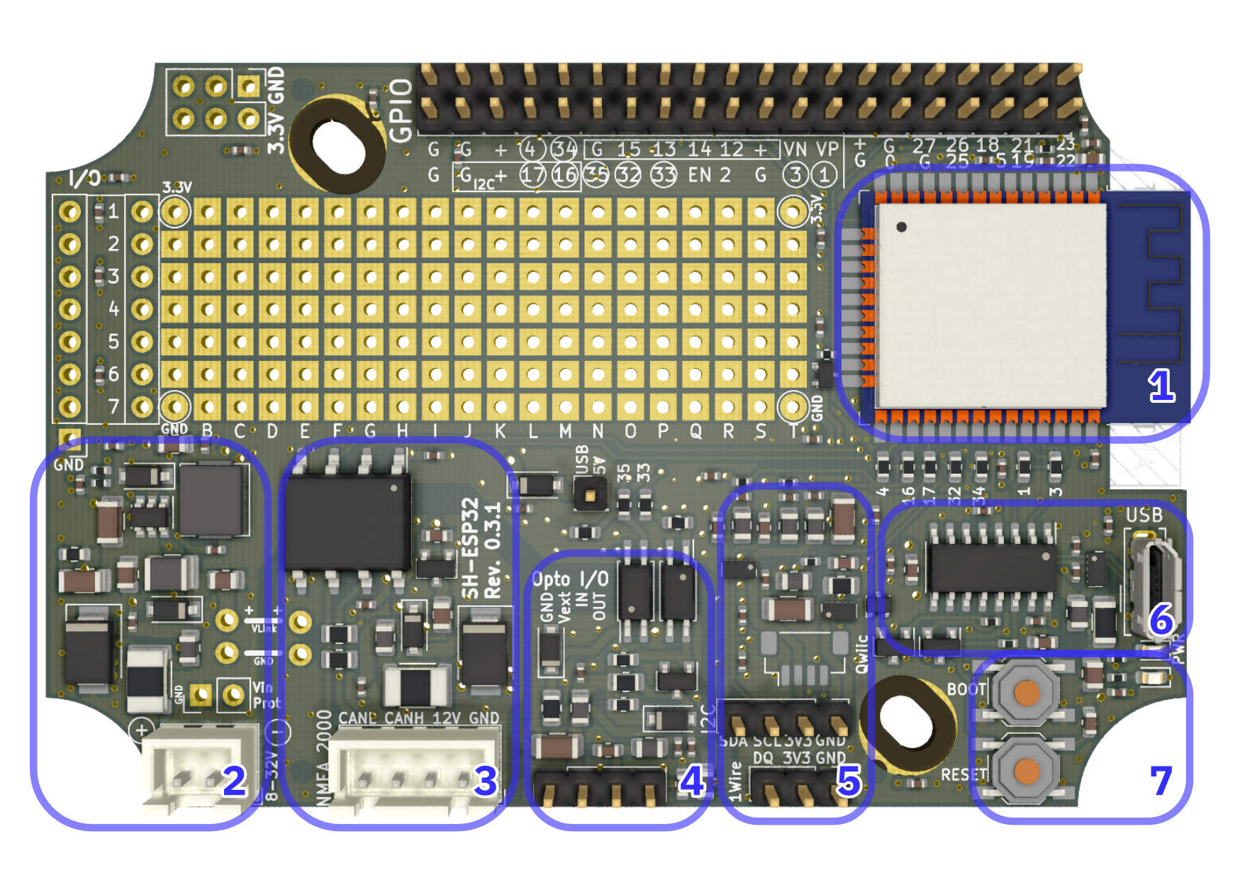
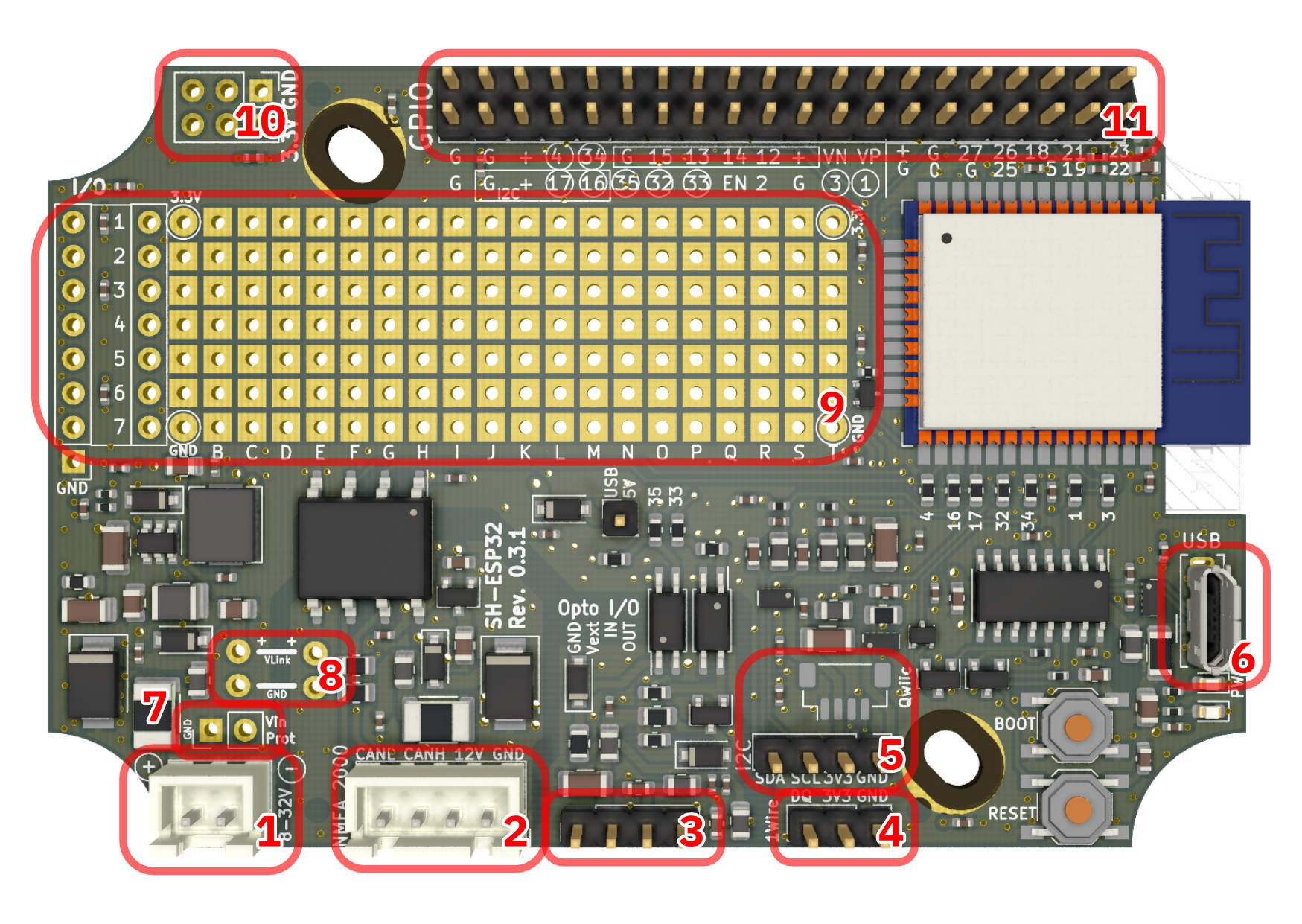
The different functional blocks of SH-ESP32 are shown below.
-
The ESP32-WROOM-32 module: The ESP32 microcontroller module is the heart of the device. It contains the two-core microcontroller with integrated RAM, a flash chip, and a WiFi/Bluetooth antenna (or, in the case of SH-ESP32-ufl, a U.FL connector for the antenna).
-
Power supply: SH-ESP32 has an integrated switching mode power supply that converts input voltages between 8V and 32V to the 3.3V voltage used on the board. The power supply also includes a self-resetting 500 mA polyfuse, reverse polarity protection, and surge protection.
-
CAN bus transceiver: SH-ESP32 includes an isolated CAN transceiver that conforms to the NMEA 2000 specification. The CAN bus circuitry also includes protection similar to the main power supply and a 5V linear regulator to power the transceiver independently from the NMEA 2000 bus.
-
Optocoupler input and output: Optocoupler I/O can be used to connect the SH-ESP32 safely to noisy external inputs or outputs such as the alternator signal or relays.
-
I2C and 1-Wire I/O: SH-ESP32 supports 1-Wire and I2C on separate 2.54 mm headers. Additionally, there is an unpopulated footprint for a Qwiic compatible JST SH connector. Both interfaces are ESD protected and have noise filtering.
-
USB interface: SH-ESP32 has a USB 2.0 compatible Micro B connector and interface. When connected to a host computer, the board is visible as a USB serial device. The USB interface can be used for powering the board, flashing the ESP32 module, and for communicating with the device using a serial protocol.
-
User interface: There are two buttons and two leds integrated on the board. The reset button resets the board. The boot button can be used to force the ESP32 into a flashing mode, and otherwise is usable as a generic button input on GPIO0. The red LED is hard-wired to the 3.3V power, indicating that the device is powered, while the blue LED is connected to GPIO2 and can be controlled by the program.
Connectors
The picture below illustrates the different connectors on the SH-ESP32. The connectors are as follows:
-
Power connector: A JST XH compatible power connector. A 2.5 mm terminal block can be fitted on the same footprint.
-
CAN bus connector: A 4-pin JST XH connector designed to be connected to a standard NMEA 2000 compatible DeviceNet M12 connector on the enclosure.
-
Optocoupler I/O header: Optocoupler input and output can be provided via this interface. The labels for these four pins are a bit "north" on the board: GND, Vext, IN, and OUT.
-
1-Wire header: 1-Wire interface fitted with ESD protection and noise filtering as well as low-pass filtering required for longer networks. No other circuitry is required for connecting 1-Wire devices to the SH-ESP32. The 1-Wire data in pin (labeled "DQ" on the board is connected to GPIO 4, so in your program, use GPIO 4 as your 1-Wire input pin.)
-
I2C header: Four-pin header for connecting I2C slave devices to the SH-ESP32. A female header accepts many popular inexpensive OLED display modules using the SSD1306 driver as is.
There is also an unpopulated Qwiic-compatible JST SH footprint next to the 2.54 mm header.
-
USB: This is your standard USB Micro B connector.
-
Protected Voltage: These header pads can be used to provide input voltage that has been reverse polarity and surge protected. For example, if you're powering the board with ~12V, the + pin of these pads will provide ~12V. Observe the polarity: it is opposite of the nearby power input connector.
-
Voltage link: If you intend to power the board using the NMEA 2000 interface and don't need galvanic connections to external systems, you can connect these pads together to route the power from the CAN bus connector to the main power supply.
-
Proto board area: This area can be used for your custom modifications.
-
Additional voltage output: Use these pads to get additional GND and 3.3V voltage output for any modifications you need. Note that despite what the silkscreen might suggest, the top three pins are all GND and the bottom three are all 3.3V.
-
GPIO header: The GPIO header provides connections to all GPIO pins available on the ESP32 module. Some of the pins are used by other peripherals by default and need to be enabled using the solder jumpers.
ESP32 module
ESP32 is a series of low-cost, low-power microcontrollers and microcontroller modules created and developed by Espressif Systems, a Shanghai-based Chinese company. The ESP32-WROOM-32 module is built around a powerful dual-core Tensilica Xtensa LX6 microprocessor and features integrated WiFi, dual-mode Bluetooth, and a remarkable amount of peripherals.
The SH-ESP32 features an ESP32-WROOM-32E module with an integrated PCB antenna, while the SH-ESP32-ufl uses ESP32-WROOM-32U that has an U.FL connector for an external antenna.
For more information, visit the ESP32 Wikipedia article, Espressif's product pages, or read the module datasheet.
Power supply
SH-ESP32 is designed to be used on a boat as easily as possible and includes an 8-32 V switching mode power supply with a maximum efficiency of nearly 90%. The power supply has a 3.3 V output with sufficient output current capability for powering both the ESP32 peak power consumption and any reasonable add-ons.
The power supply includes a self-resetting 500 mA polyfuse, reverse polarity protection, and a hefty TVS protection diode that has a breakdown voltage of 36.7-40.6V and maximum peak pulse dissipation capacity in excess of 600W. Additionally, the power supply includes EMC filtering, designed to keep the conducted emissions of the switching-mode power supply below the regulatory limits.
The switcher IC is Silergy SY8401 that has a wide input range of 4.5-60 V and a maximum output current of 0.8 A.
Peripherals
Buttons and LEDs
There are two buttons and two LEDs on the SH-ESP32. The two buttons are labeled Reset and Boot. The Reset button resets the board by pulling the ESP32 Enable pin low. The Boot button is connected to GPIO0 and can be used during device startup to force the module into a download mode. Otherwise it can be used as a regular button input.
The two LEDs are not explicitly labeled. The red LED is lit whenever there is 3.3V power on the board. The blue LED is connected to GPIO2 (the pin commonly used for LED on ESP32 development boards). It can be controlled by user programs to indicate the state of the device.
USB
The USB interface can be used to reprogram the ESP32 module and to communicate with the user application. It also powers the board when plugged in. The board can be safely powered using the main power connector and USB simultaneously -- rectifying diodes ensure that only the highest voltage supply is used.
The USB interface is implemented using a low-cost CH340C USB to serial interface chip. It emulates a standard serial interface with bit rates of up to 2 Mbps.
CH340 chips are natively supported by Linux kernels but require a driver on Mac and Windows. The driver can be downloaded from the manufacturer website.
CAN bus (NMEA 2000)
NMEA 2000 is a ubiquitous communications standard used for connecting sensor, control, and display devices on boats and ships. It is based on the Controller Area Network (CAN bus) which is a vehicle bus standard designed to allow devices to communicate with each other without a host computer.
SH-ESP32 includes an isolated CAN bus interface that allows safe and NMEA 2000 compliant interconnection of devices. The CAN bus interface can be used to directly output sensor readings to the NMEA 2000 network, or to build NMEA 2000 gateways or similar devices.
The CAN interface uses ESP32's integrated CAN controller and the ISO1050DUB isolated CAN transceiver by Texas Instruments. It features support for high isolation voltages and transients, and bit rates of up to 1 Mbps.
The CAN bus interface can also be used to power the whole device if there are no galvanic connections to other external systems. (FIXME: Needs a more thorough description and illustration.)
The CAN interface includes a built-in termination resistor that can be enabled by closing the "CAN term" solder jumper on the bottom side of the board.
I2C
I2C (Inter-Integrated Circuit) is a very popular synchronous serial communication bus commonly used for interfacing with a number of different ICs. It uses two data wires in addition to voltage and ground.
I2C can be used to connect a large number of devices to the SH-ESP32. Device types include analog-to-digital converters, attitude sensors, temperature and humidity sensors, displays, keypads, GPS, and so on. Any Qwiic-compatible board from SparkFun can be used with the SH-ESP32 by splicing the wires or by adding a JST SH compatible connector to the available footprint.
Maximum I2C bus distances depend on the load, but should be less than 3-4 m. There are better suited protocols for long distance communication.
1-Wire
1-Wire is a device communications bus system designed by Dallas Semiconductor, since acquired by Maxim Integrated Products. Although 1-Wire is a slow-speed protocol, supporting only speeds up to 16.3 kbps, it is very simple to implement and can be used over long distances. It is commonly used for temperature sensors and similar simple sensing devices.
The SH-ESP32 1-Wire implementation features ESD and RF noise filtering as well as low-pass filtering to improve network reliability.
Note that the 1-Wire data pin (labeled "DQ") is physically mapped to GPIO4, so in your program, use GPIO4 for all 1-Wire data.
Optocoupler input and output
Optocoupler input and output is the recommended way to add simple digital signal input and output and sensing to different external systems. It can be used e.g. to count alternator pulses for RPM measurement or switch relays on or off.
Additionally, the SH-ESP32 opto I/O implementation should be able to drive slow-speed single-side NMEA 0183 interfaces.
The absolute maximum voltage for the optocoupler input is 18V but it can be extended by adding an additional current-limiting resistor in series to the input.
If you provide a voltage between about 2.5V and 18V in ISO IN, you'll have the output of the input optocoupler pulled high, meaning that OPTO_IN (GPIO 35) is pulled high.
Likewise, if you pull OPTO_OUT (GPIO 33) high, that will make the ISO_OUT pin be driven to the voltage you have supplied to the Vext pin.
It is possible to drive small automotive relays using the optocoupler output. In that case, the solenoid pins should be connected to the Vext and OUT pins.
GPIO header
The GPIO header can be used to access all GPIO pins of the ESP32 module. The silkscreen labeling next to the header refers to the GPIO numbers of the pins.
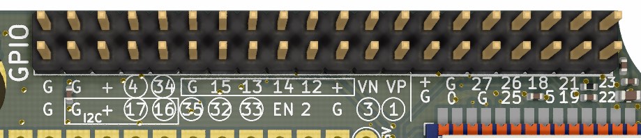
Circled numbers are by default used by other peripherals and have to be connected by setting the solder jumpers (see Section "Customizing GPIO assignments" for more information).
The pin group including GPIOs 16 and 17 encapsulated by a rectangle can be used as duplicate I2C header if the respective solder jumpers are closed.
The pin group with GPIOs 12-15 can be used as a JTAG connector with some simple external hardware and software. JTAG is an industry-standard debugging interface for microcontrollers and other programmable devices that allows on-chip debugging, including setting hardware breakpoints, stepping through code and inspecting live variable values.
Finally, the pin group consisting of the 14 pins on the right end of the header will be used by an Ethernet add-on board.
No ESD, RF noise protection or other filtering is provided for the GPIO header pins.
Proto board area
The large open area in the middle of the SH-ESP32 is the proto board area. It can be used to add new functionality via embedded 3rd party modules or THT circuitry. Layer fills or traces on the inner copper layers are on purpose avoiding the proto board area, and the area can be safely drilled or modified to accept larger components, if needed. There are traces very close to the area, however, so some care should be taken when modifying the pads at the border of the area.
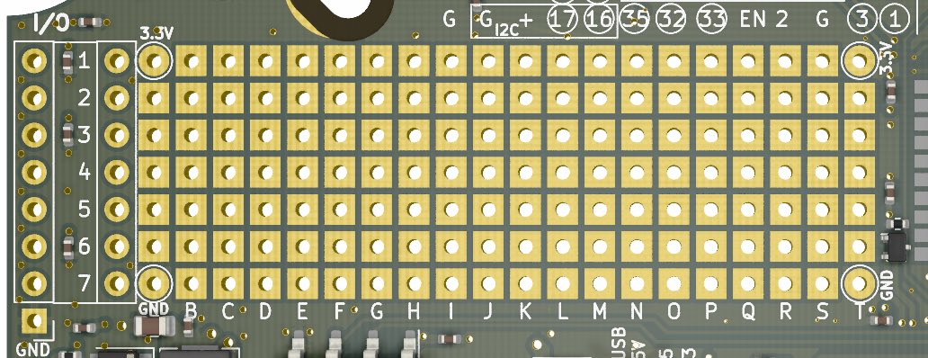
The round pads to the left hand side that are labeled 1 - 7 are horizontally connected. That is, the round pad on the left side of the label "1" is connected to the round pad on the right side of the label "1", and so on for 2 - 7. This is to make it easier to place a header on the PCB edge. You can place a header on the row at the edge and make connections to the inner row of round pads.
Pinouts of peripherals
The ESP32 has a GPIO matrix that allows most of the digital GPIO functionality to be mapped freely to any GPIO. This is utilized extensively on SH-ESP32, and few peripherals are mapped to their standard pins. The GPIO pinout of different peripherals is given below. Unlisted pins are not used by SH-ESP32 and can be utilized freely.
The GPIOs having a mark in the Jumper column are, by default, connected to the respective peripheral and disconnected from the GPIO header. These connections may be altered by modifying the jumpers as described in Section "Customizing GPIO assignments". For example, GPIO4 is circled on the board, and in the table below, there is an "X" in the Jumper column, and "1-Wire data" in the Function column. This means that, unless you do some soldering, the pin that's labeled 4 isn't connected to anything, because the 1-Wire data pin ("DQ") is connected to GPIO4 by default.
The ADC column lists pins connected to either of the ESP32's two ADCs. ADC2 is used by the WiFi, so if WiFi is in use, ADC2 cannot be used.
Touch N refer to the capacitive touch sensor inputs.
| GPIO # | Jumper | ADC | Function | Optional Function |
|---|---|---|---|---|
| 00 | 2 | BOOT | Ethernet REF_CLK; Touch 1 | |
| 01 | x | Serial TXD0 | ||
| 02 | 2 | Blue LED | Touch 2 | |
| 03 | x | Serial RXD0 | ||
| 04 | x | 2 | 1-Wire data | Touch 0 |
| 05 | Free | Ethernet Reset_N | ||
| 12 | 2 | Free | JTAG TDI; Touch 5 | |
| 13 | Free | JTAG TCK; Touch 4 | ||
| 14 | 2 | Free | JTAG TMS; Touch 6 | |
| 15 | 2 | Free | JTAG TDO; Touch 3 | |
| 16 | x | I2C SDA | ||
| 17 | x | I2C SCL | ||
| 18 | Free | Ethernet MDIO | ||
| 19 | Free | Ethernet TXD[0] | ||
| 21 | Free | Ethernet TX_EN | ||
| 22 | Free | Ethernet TXD[1] | ||
| 23 | Free | Ethernet MDC | ||
| 25 | 2 | Free | Ethernet RXD[0] | |
| 26 | 2 | Free | Ethernet RXD[1] | |
| 27 | 2 | Free | Ethernet CRS_DV; Touch 7 | |
| 32 | x | 1 | CAN TX | Touch 9 |
| 33 | x | 1 | Opto OUT | Touch 8 |
| 34 | x | 1 | CAN RX, input only | |
| 35 | x | 1 | Opto IN, input only | |
| 36 (VP) | 1 | Free, input only | ||
| 39 (VN) | 1 | Free, input only |
This page provides a great description of the different ESP32 GPIOs and their availability.
Customizing GPIO assignments
Nearly all hard-wired peripherals can be disconnected by unsoldering a 0R resistor jumper on the board top layer. In a similar fashion, the solder jumpers on the bottom layer can be closed to connect the GPIO pin to the respective GPIO header pin. The resistor and solder jumpers are illustrated in figures below.
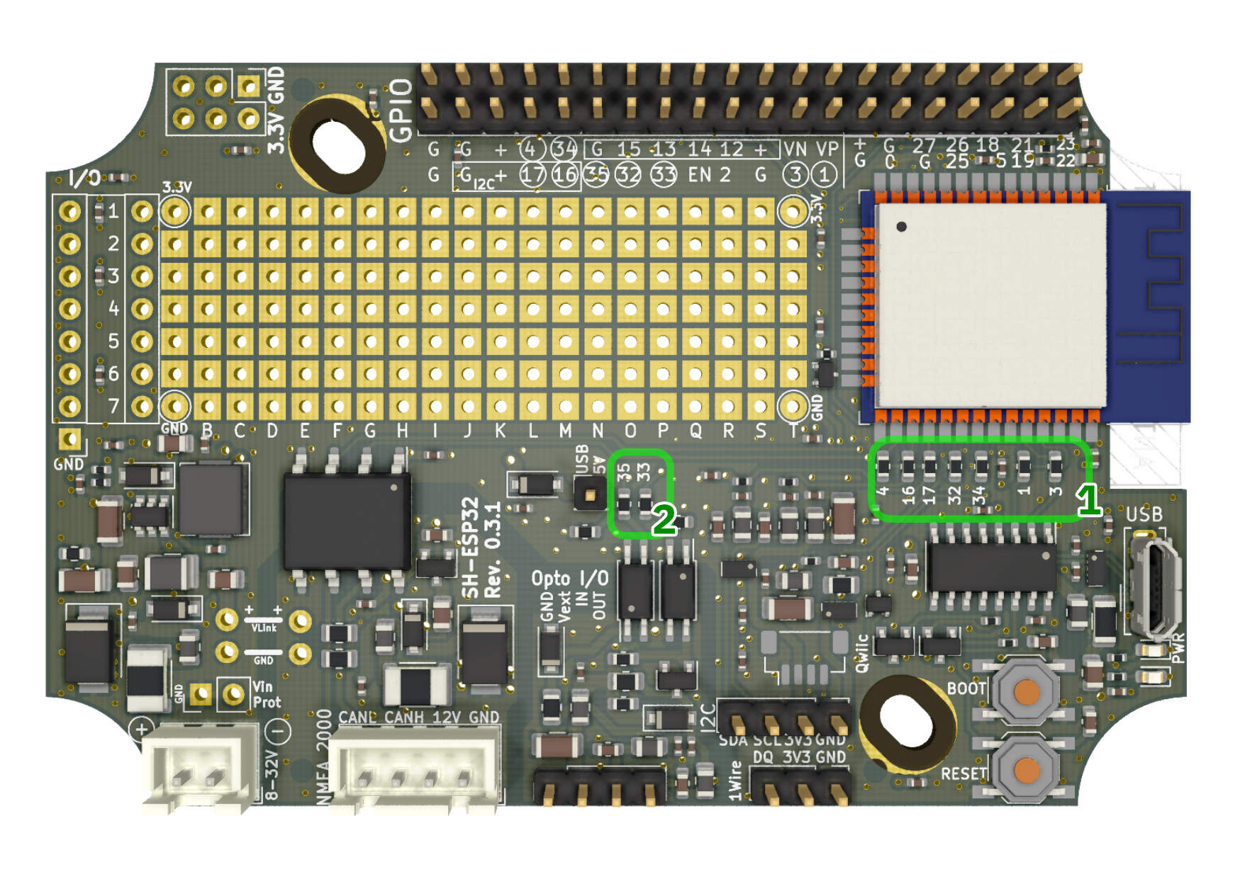
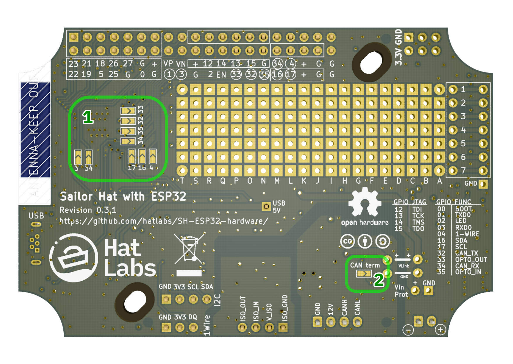
For example, if don't need the CAN interface and want to reuse the GPIOs 32 and 34 on the GPIO header, desolder the resistors labeled 32 and 34 next to the ESP32 module to disconnect the module from the CAN interface. Then close the solder jumpers labeled 32 and 34 to connect the GPIO pins to the GPIO header.
Likewise, if you want to enable I2C both on the GPIO header and the dedicated I2C connector, close the solder jumpers 16 and 17 on the board bottom layer.
Finally, the jumpers on either side can be used to customize the GPIO assignments. For example, if you want to swap 1-Wire data pin from GPIO4 to GPIO15, you can unsolder the GPIO4 resistor jumper and add a jumper wire from either the ESP32 module pad or the GPIO header to the lower resistor jumper pad.
Note: The silkscreen labeling for GPIO 1 and 3 solder jumpers is incorrect in revision 0.3.1 devices. They are labeled 3 and 34 while the correct labeling is 1 and 3.
Software
Introduction
There are a lot of options for languages and environments for writing software for SH-ESP32. If you don't know where to start, using Visual Studio Code and PlatformIO and SensESP are the recommended choices, but depending on your needs and preferences, you might want to try other options as well.
SDKs
There are multiple Software Development Kits (SDKs) available for the ESP32 environment. All of these are compatible with the SH-ESP32.
Espressif SDK is the official C++ programming environment. It has a C style API that does not rely on classes or objects. It also exposes FreeRTOS, the underlying Real-time Operating System directly. As the official development environment, Espressif SDK provides the most complete access to ESP32 functionality.
Espressif SDK uses CMake as its build system.
Arduino Core for ESP32 is an Arduino SDK for the ESP32. It is also maintained by Espressif and, thanks to the breadth of the Arduino ecosystem and related documentation, is probably the most widely used SDK for ESP32.
The Arduino Core can be used either with Arduino IDE, or PlatformIO.
Arduino IDE is a beginner-friendly software development environment originally developed for the Arduino brand hobbyist developer boards. It is very easy to start with but the editor is ill-suited for more serious software development, and it also has inherent limits in library and environment management. Also, it uses its own build system and project layout which is incompatible with other systems. It is a good choice for very simple single-purpose sketches, but for more complex projects or integrating with e.g. Signal K or other server protocol, look further.
PlatformIO is a cross-platform development environment for different microcontrollers. It can be used purely on the command line but also integrates well into Visual Studio Code, which is an excellent multi-language code editor and development environment. PlatformIO performs library management and dependency resolution and also includes support for hardware debuggers and more.
If you want to develop the SH-ESP32 using higher-level languages, MicroPython is a good choice. It provides high compatibility with normal Python while running on the FreeRTOS. There are ready-made modules for many ESP32 subsystems and peripherals.
NodeMCU is a yet another SDK available for the ESP32. NodeMCU is based on lua, which is a lightweight programming language designed primarily for embedded use in applications. NodeMCU was previously popular in ESP8266 development but has since become eclipsed by the more popular programming environments.
Rust is yet another programming language choice for the Espressif microcontrollers. Rust is a modern language that has excellent features for systems programming but the ESP32 support is still under heavy development and the documentation is lacking.
Application frameworks
When you start developing your C or C++ application for integrating onto Signal K or NMEA 2000, it usually pays off to use some existing library or framework as a stepping stone. As of now (March 2021), the two prime candidates are SensESP and ESPHome. SensESP, described in the subsection below, is a set of libraries designed to easily integrate sensor devices into the Signal K system but has a lot of features for general purpose embedded development as well. ESPHome is a system designed to control ESP devices using simple configuration files and has good integration to multiple home automation platforms.
SensESP
SensESP is a sensor development platform for ESP8266 and ESP32 that can be used as a high-level toolkit for creating hardware devices interfacing with Signal K servers. It can be easily integrated with NMEA 2000 networks and has a lot of helpful features for asynchronous embedded programming, such as extensive use of the consumer-producer pattern and high level concepts of Sensors, Translations and Consumers (Outputs).
Add-on boards
There are several add-on boards available or being developed for the SH-ESP32.
Proto Board Top HAT is a add-on board the size of SH-ESP32 that plugs onto it and provides ample area for user customizations. It is available for purchase at the Hat Labs store. The design files are available at the SH-ESP32 hardware repository.
Several other hats such as a digital switching PowerFET HAT or an Ethernet HAT are under development.
If you want to develop your own SH-ESP32 hat, a blank hat template is available at the SH-ESP32 repository.
Tutorials
Tutorials and example projects
Some tutorials and example projects using the SH-ESP32 are given below.
NMEA 2000 USB gateway
Introduction
In this tutorial, I'll show how to build an Actisense™1 NGT-1 compatible NMEA 2000 USB gateway with an SH-ESP32 and a couple of connectors. Thanks to the SH-ESP32's integrated CAN interface, no external hardware is required. The resulting device is an isolated NMEA 2000 gateway that will both read and write NMEA 2000 packets and allow your computer to interface with your boat electronics. The NMEA 2000 gateway could be used to interface any major PC based navigational software with your NMEA 2000 network, or to connect a Raspberry Pi based Signal K server to the NMEA 2000 bus, or even to diagnose NMEA 2000 issues with suitable software.
If you have any suggestions, corrections, improvement ideas, or other feedback about this tutorial, I'd love to hear about them at matti.airas@hatlabs.fi.
Parts needed
To complete this tutorial, you need the following parts:
- SH-ESP32 enclosure bundle
- NMEA 2000 male panel connector
- USB panel connector (soon to be available at hatlabs.fi) or a PG9 cable gland
- OLED display (optional)
Hardware assembly
Required accessories
We'll use the standard waterproof SH-ESP32 enclosure for this project.
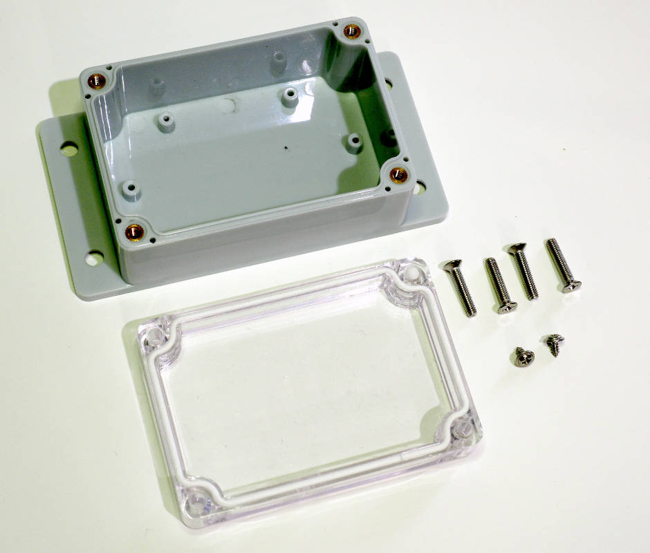
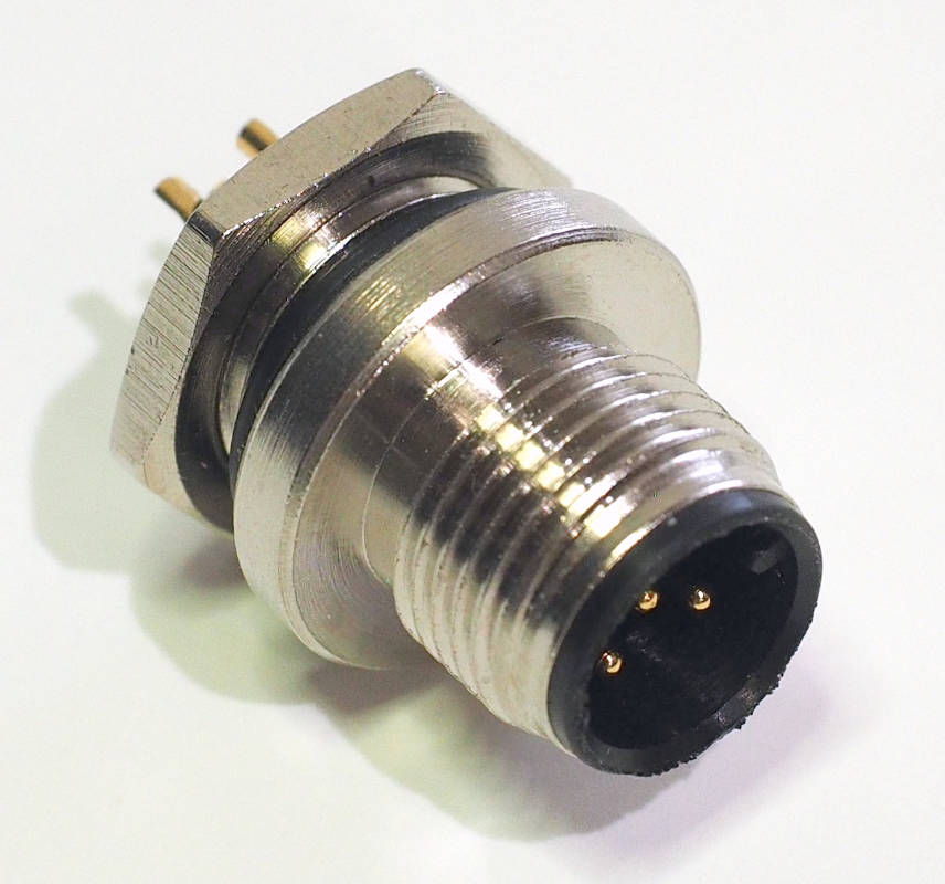
We need to connect the device to both NMEA 2000 and USB. For NMEA 2000, a standard M12 micro connector is used.
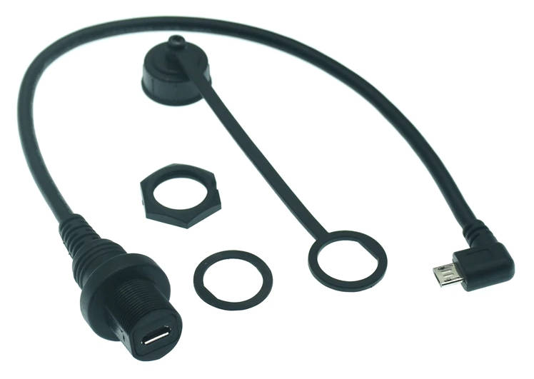
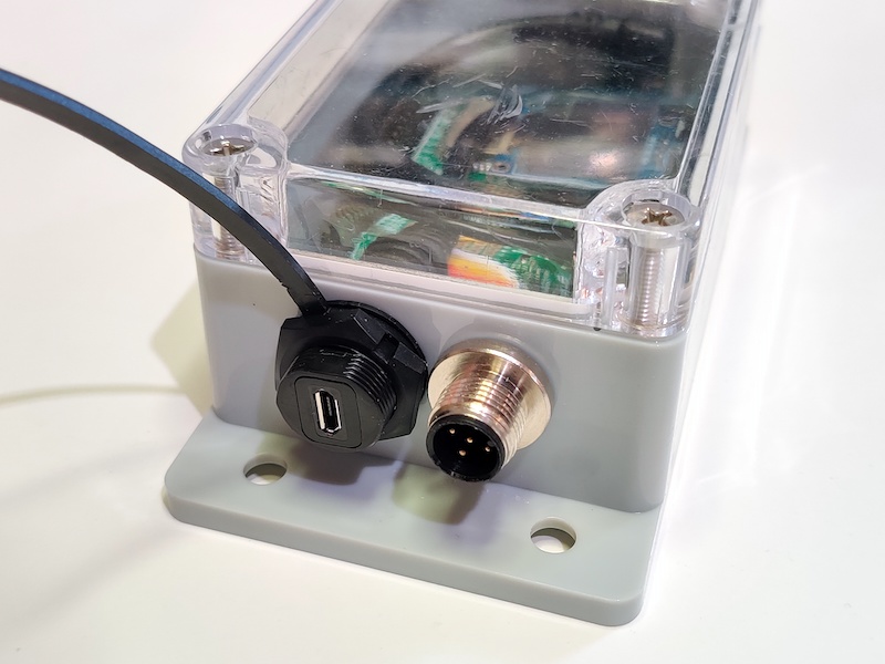
For the USB connector, the preferred option is to use a ready-made micro USB panel connector:
Another option would be to use a cable gland to route a micro USB cable to the enclosure. That's the option I chose, mainly because I hadn't yet received the panel connector shipment I was waiting for. Using a cable gland with a ready-made cable is a fiddly process, though. I had to drill out the internal collar on the cable gland and enlarge the hole on the gland cap nut. To make the big PG9 cable gland grip on the thin USB cable, I wrapped a few rounds of PVC tape over the cable. The end result is a bit hacky but good enough for government work!
Drilling holes
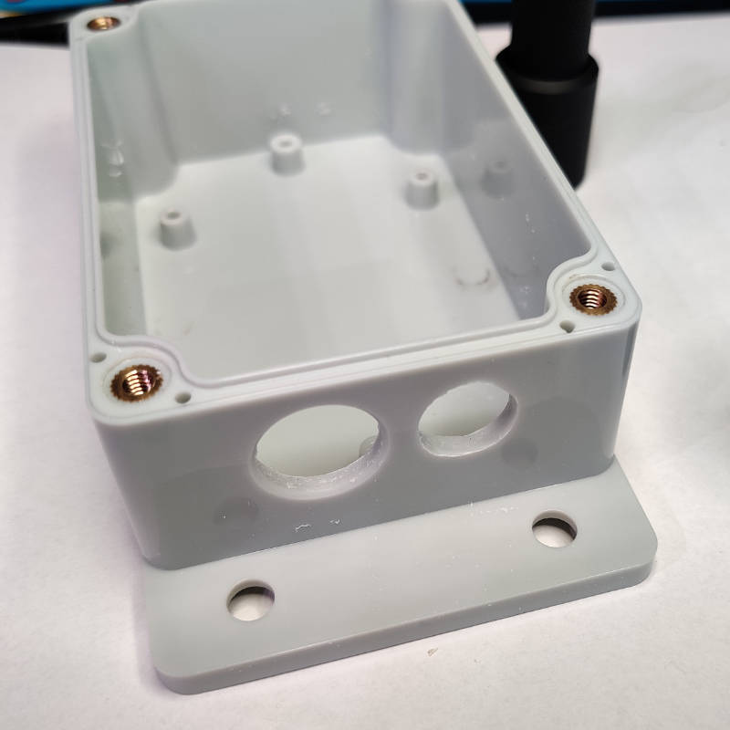
You need to decide where to place the connectors on the enclosure. I prefer having the connectors both on the same short edge. That allows the enclosure to be mounted on a wall connectors facing down. Such an orientation minimizes the risk for water leaking through the connector seal.
Connector placement is a tight fit. When marking the center points, take into account both the enclosure inner corners and the needed spacing to allow the connector nuts to rotate. A sample result is shown in the photo below.
Connecting wires to the NMEA 2000 panel connector
The NMEA 2000 connector requires the wires to be soldered to it. I am using the provided JST XH connectors and pigtails. The pigtail follows the NMEA 2000 standard color scheme, except that the L signal wire is yellow instead of the standard blue.
The connector pins have small cups, as shown in the photo below:
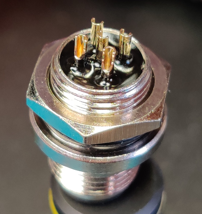
Heat the pins one at a time with the solder iron and apply some solder to the cups.
Before attaching the wires, cut small lengths of heat shrink tube and slide it over the wires. You want to have the heat shrink tube because it will add some mechanical support on the wires in addition to preventing accidental shorts.
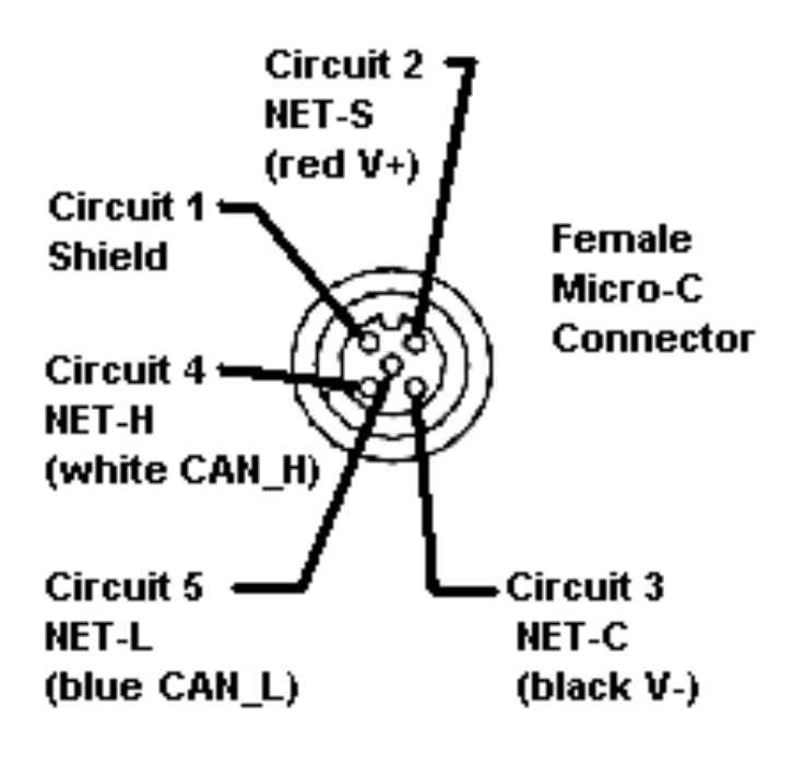
Pay close attention to the correct pin ordering. The correct pinout, when observing from the side you're soldering the wires on, is shown in the figure below. (The figure says "female connector" but that's when you're staring at the front side of the connector.)
I repeat, pay close attention to the correct pin ordering. When preparing this tutorial, I first applied all the pins mirrored (following a male connector pinout diagram). It wouldn't work, of course. At the next attempt, I had the H and L pins swapped. Still wouldn't work. Third attempt, I had the pins in the correct order but I had forgot to replace the heat shrink tube. On the fourth attempt, I got it right. Be unlike me! Focus when you're soldering the connectors!
To solder the wires to the pins, take the pigtail, and one pin at a time, heat the pin so that the solder melts and insert the wire end to the solder-filled cup. Start with the center pin first because it's easier to put on before the other wires are in the way.
Once all wires are attached, let the connections cool a bit and then slide the heat shrink tubes over the pins. To heat the tubes, a hot air soldering workstation or a hot air gun are ideal, but even a lighter flame will do. If you're using a flame, be just sure not to overdo it. You don't want charring on the heat shrink tubes.
An example end result is shown in the following figure.
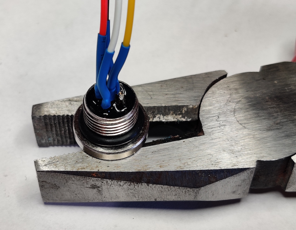
The photo also shows one trick of mine: for soldering many types of connectors, sturdy pliers and some rubber band keep the connector perfectly still when soldering. I find that easier than using the cheap helping hands I have.
Assembly
Finally, screw the NMEA 2000 panel connector in place. Tightening it properly can be bothersome, but no matter what you do, do not apply locktite to the connector. If any locktite gets on the ABS plastic, it'll turn all brittle and disintegrate from the slightest breeze! Trust me! Instead, a drop of superglue might work once you've verified that everything works. Or maybe a tiny drop of acetone between the enclosure plastic and the connector body. Acetone softens ABS and turns it into a sticky glue-like substance.
Also put on the cable gland and the USB cable (or the USB panel connector). A cable with a straight connector is a bit of a tight fit but I doubt an angled connector would have fit through the cable gland. Despite measuring twice, I still had drilled the holes too close to each other, and the nut wouldn't rotate freely. Instead, I was able to twist the gland body to tighten it up. It's not perfect but will work fine.
If you want to use an OLED display, plug it in now.
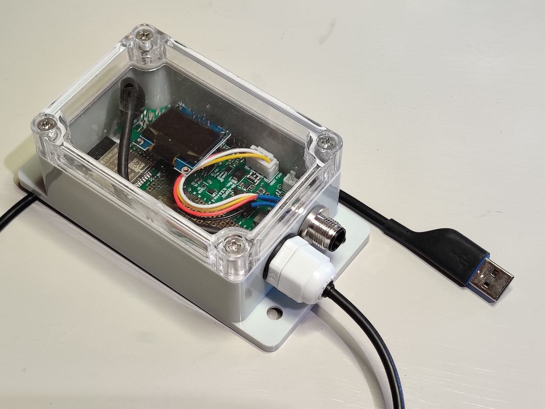
The end result is shown in the photo below.
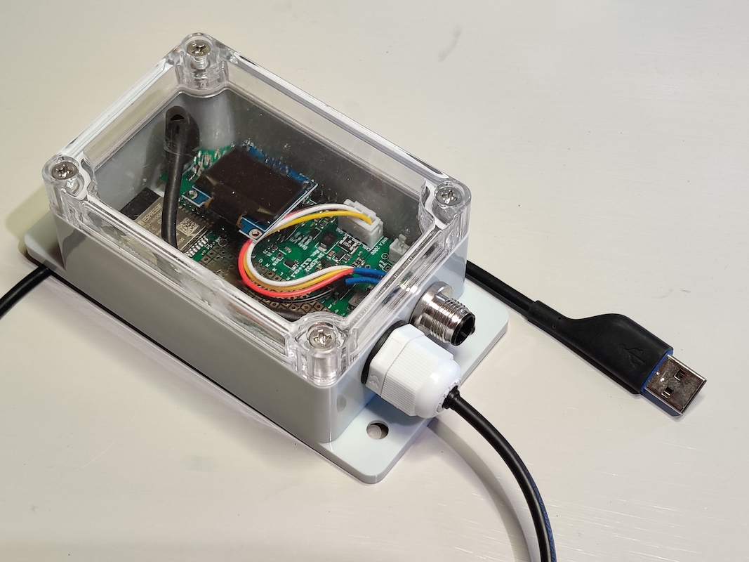
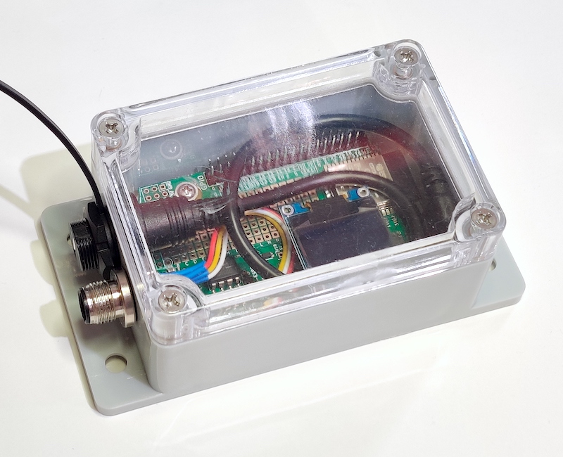
Another, arguably neater way of getting the USB connection through the enclosure is using a USB panel connector. That lets you sidestep all fiddling around with the cable glands. All the same considerations with drilling the holes too close to each other still apply, though...
Software
Prerequisites
To install the software on the device, you need to first install Visual Studio Code and PlatformIO.
Another prerequisite is the driver for the CH340 USB serial chip. Linux supports it out of the box but Windows and Mac users need to download and install the driver from the manufacturer website. The driver is used both for installing the software and using it.
Installation
The SH-ESP32 NMEA 2000 USB gateway software is available here: https://github.com/hatlabs/SH-ESP32-nmea2000-gateway
Once you have PlatformIO installed, clone the repo (if you're comfortable with Git) or download the source code as a zip file by clicking on the green "Code" button and selecting "Download ZIP". Unzip the package and open the directory in Visual Studio Code (File -> Open Workspace). Connect the USB cable to your computer. Then, click on the PlatformIO bug icon (shown below) on the left border toolbar. Select Default -> Upload. You should see the build system and compiler output scroll at the bottom part of the screen as PlatformIO downloads the dependencies and builds everything. Once everything is built, PlatformIO should proceed with uploading the software on your SH-ESP32.
If you want to personalize your device, open the src/main.cpp file in VSCode and edit the device information strings around line 74.
Those strings will be seen by other NMEA 2000 devices on the network.
If everything went fine, the blue led should start blinking slowly. If you have a display, you should also see some status information there.
Testing
If you plug the device to your NMEA 2000 network and your computer, you should immediately see the RX row on the display change. That indicates how many NMEA 2000 messages have been received every second. The TX row tells how many messages have been sent, but if you aren't running any software yet, it'll be zero.
I chose to test the device with Signal K Server. You can install Signal K Server on a Raspberry Pi but for this purpose I installed it on my Mac laptop. Linux and Windows should work too. Basic installation instructions are available at the server GitHub repository: https://github.com/SignalK/signalk-server
I'm assuming you have managed to install and run the server and have browsed to the web UI now. Right?
To enable the device, you need to add an NMEA 2000 data connection. Select Server -> Data Connections. Click on the blue Add button.
You should now see the following form.
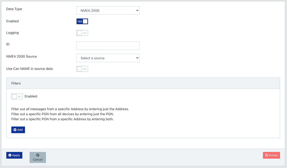
Select "NMEA 2000" as the data type.
Provider ID can be any string.
can0 is fine.
NMEA 2000 Source should be "Actisense NGT-1 (canboatjs)".
Click on the serial port selection (by default "Enter manually").
If your device was detected, you should see a device name there.
The device names are pretty uninformative.
On my Mac, the device shows itself as /dev/tty.usbserial-14130 or similar.
On a Linux, it should be something roughly similar.
On Windows, the format is COMn:.
Select the device.
Everything else can be left as is.
Click Apply to save the changes.
Next, restart the server by clicking the Restart link at the top bar. If you had started the Signal K server manually, you might now have to restart it on the command line.
If all went fine, you should have can0 displayed in the "Connection & Plugin Status" section.
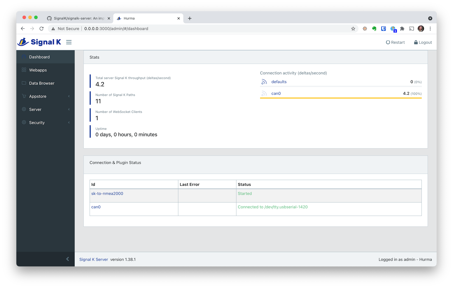
If your connection status is green, open the Data Browser and marvel at the received NMEA 2000 data!

Almost there.
You still want to test that transmitting data works too.
To get the Signal K server to transmit NMEA 2000 data, you need to install the signalk-to-nmea2000 plugin.
Select Appstore -> Available and then change the type dropdown value from New/Updated to All.
Type nmea2000 to the search box.
You should see the correct plugin as the only entry.
Install it by clicking on the small cloud download icon at the right end of the row.
Restart the server again.
Finally, configure the plugin: Server -> Plugin Config. Open the "Signal K to NMEA 2000" section. The default server installation doesn't have much data to transmit, but there's something: system time! Scroll down to "System Time (126992)" and Enable it.
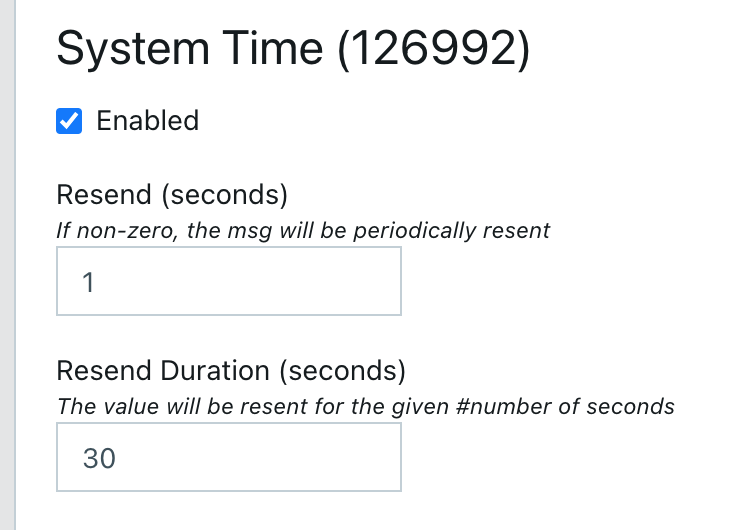
Set the Resend time to 1 second. Scroll down to the bottom of the page and select Submit.
If all the above steps went fine, you should see the TX row on the display change from 0 to 1:
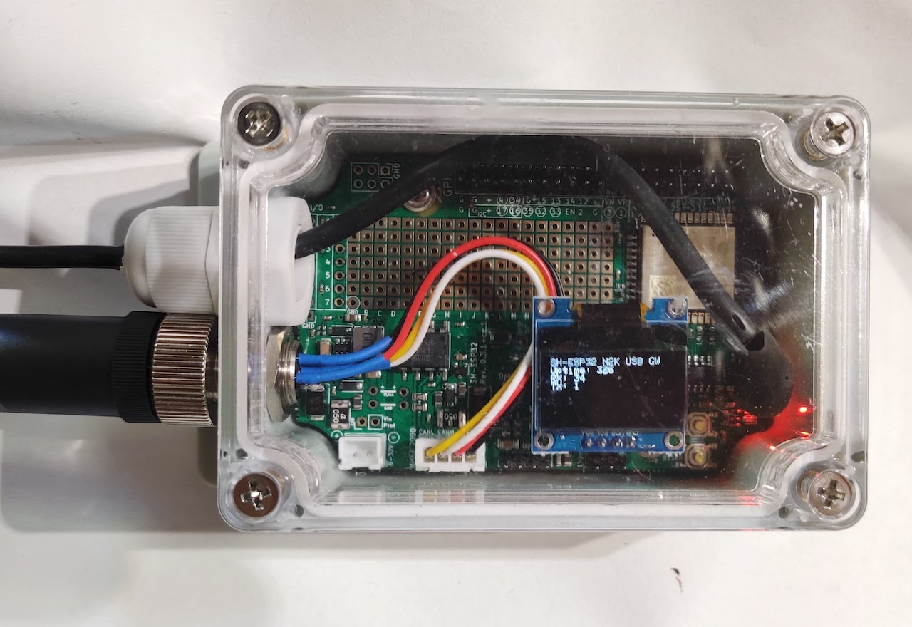
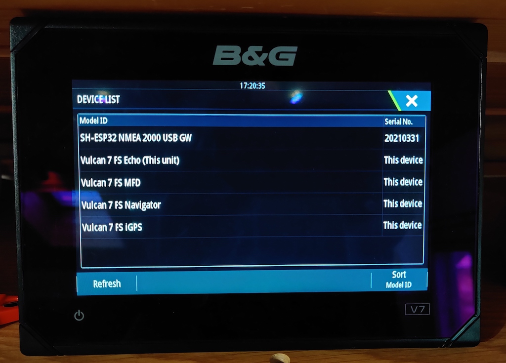
If you have a Multi-function Display (chart plotter) on your NMEA 2000 network, browse to its Network settings. On a device list page, you should now see "SH-ESP32 NMEA 2000 USB GW" among other devices! If you tap on it, you should also see the time and date as provided data. This means your installation was successful and you have data flowing back and forth! Time to go brag about it online and to your marina neighbors!
-
Actisense is a trademark of Active Research Limited. ↩
1-Wire temperature sensing
Introduction
This tutorial will walk you through creating a temperature sensing device that can be used for example to measure engine oil, coolant, and wet exhaust temperatures of of any engine that doesn't already report these temperatures to Signal K or your N2K network. My own engine is a Yanmar 3GM30F but the approach is completely generic and can be adapted to any engine. I have had a similar setup for several years and it gives me an extra peace of mind: I would get an early alarm if the temperature would begin to rise (I've had coolant issues in the past), and also if I ever would forget to open the water intake seacock, I would get an alarm of rising exhaust temperature before anything irreversible could happen.
One SH-ESP32 can support as many temperature sensors as can be practically connected to it.
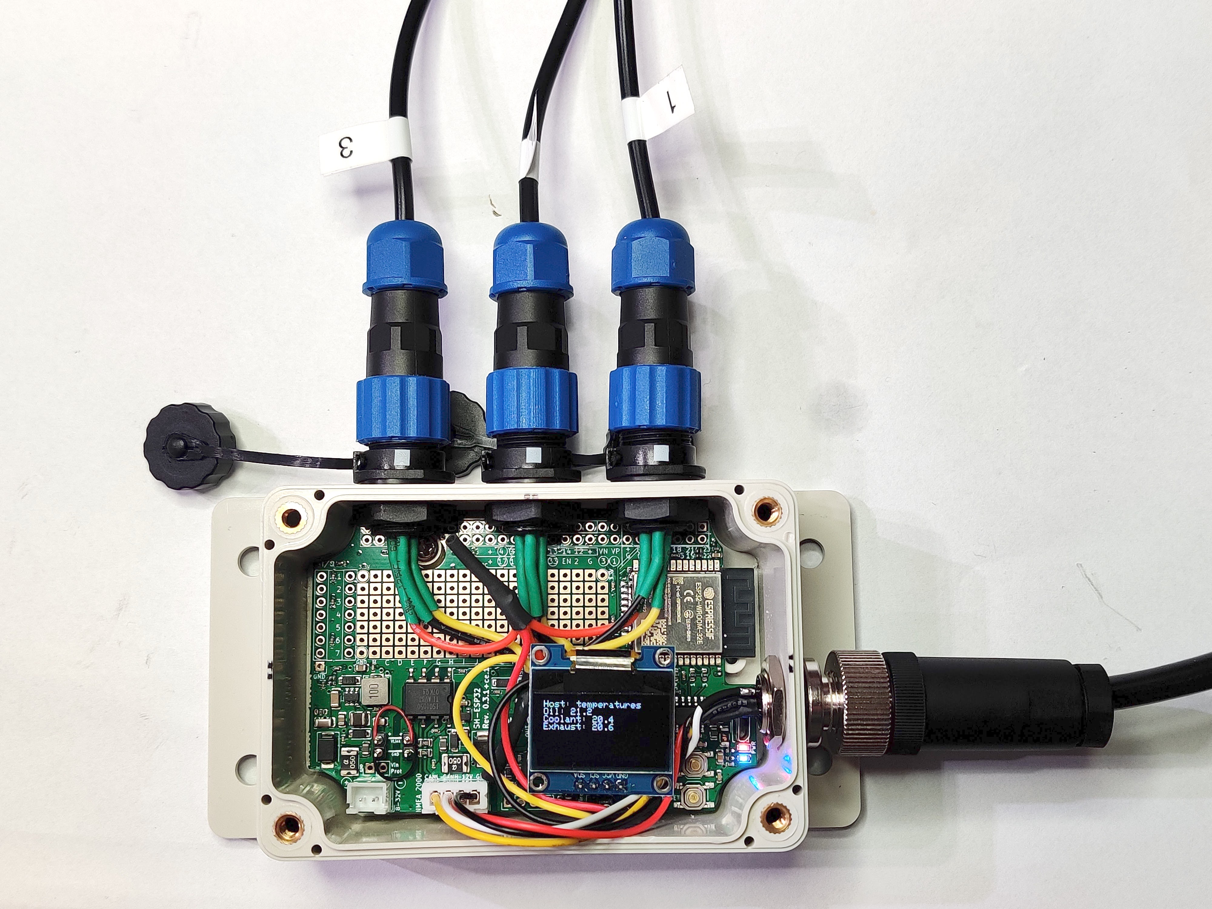
The end result of this tutorial is this neat little device that measures three different temperatures and is able to output them both wirelessly using the Signal K protocol and over NMEA 2000.
If you have any suggestions, corrections, improvement ideas, or other feedback about this tutorial, I'd love to hear about them at matti.airas@hatlabs.fi.
Parts needed
To complete this tutorial, you need the following parts:
- SH-ESP32 enclosure bundle
- 1-Wire temperature sensor -- as many as you need
- SP13 connectors, 3-pin, male plug -- as many as you want external sensors
- NMEA 2000 male panel connector -- if you want to connect the device to an NMEA 2000 network; otherwise it's Signal K only
- OLED display (optional)
Hardware assembly
I have previously had a similar setup where I spliced individual sensors together outside of the enclosure and routed them into the enclosure through a cable gland. This approach works fine but is cumbersome for maintenance. Removing the SH-ESP32 for modifications or debugging is difficult because the connections are permanent.
In this tutorial, I'll instead use separate connectors to allow for a more flexible installation.
Preparing the enclosure
The enclosure needs to have holes drilled for the different connectors. Due to the number of holes required, I prepared a printable drill template that can be taped on the enclosure.
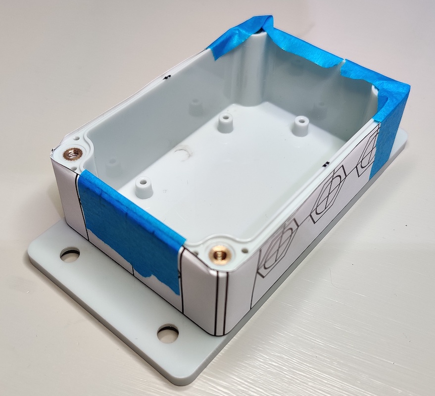
When printing the template, pay attention that it isn't scaled. The template paper size is the international standard A4, so especially North Americans should be careful not to accidentally scale the print when printing on Letter size paper.
To apply the template, first cut it out along the edges. Then mark midpoints of the enclosure sides with a felt pen. Align one side of the template with the midpoint mark and tape the end to the enclosure. Then pull the paper taut over the enclosure and ensure that the other midpoint marks are correctly aligned. Fix the template with a generous helping of tape. It doesn't matter if you tape over the template: at least masking tape is sufficiently translucent to show through the tape.
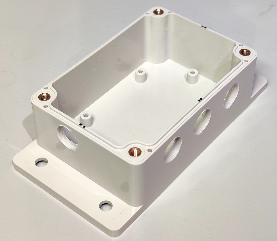
Once you have the template in place, decide where you want the connectors. If you don't have the GPIO header in place, the north edge of the SH-ESP32 has a plenty of room for connectors. The west edge is pretty vacant as well. The east side can easily fit connectors but one in the southeast corner will block the USB.
I wanted to mount my device vertically so that the power connector exits down and the temperature sensor connectors to the right. I just made the mistake of blocking the USB connector. I guess it's over-the-air updates for me, then...
Connecting wires
Connecting multiple one-wire sensors to one device is easy: you just need to connect each wire in parallel. I soldered lengths of wires on the connectors with the following pinout:
- Ground (black)
- 3.3V (red)
- Data (yellow)
Next, I stripped 12 mm (1/2") of the wire and twisted each color tails (with an extra header wire) together and applied some solder to make a simple rat-tail splice.
In the photo, the splices are without heat shrink tube but you should definitely add some to protect everything from shorting out.
DON'T DO THIS:
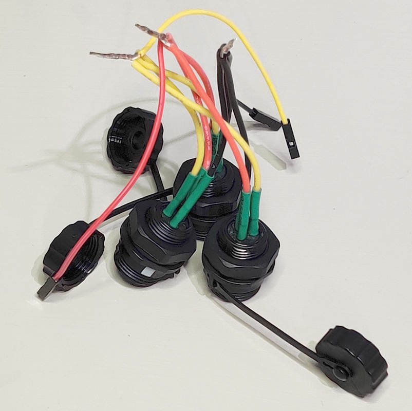
Quick, what went wrong in my attempt? Well, first, how do you get the connector nuts off? Second, how do you mount the connectors with the wires spliced together? Third, if you managed to mount the connectors, how would you get the nut back on?
Don't be like me. Instead, mount the connectors first, then splice the wires and apply some heat shrink tube.
If you want to connect the apparatus to NMEA 2000, add an M12 panel connector as described in the NMEA 2000 USB gateway tutorial. Alternatively, if you live in the future and are building a Signal K only setup, use the SP13 power connector provided in the enclosure bundle. In that case, for consistency, make ground the first pin and 12/24V the second pin.
For NMEA 2000 use, you must also provide power to the SH-ESP32 device. You could do that by splicing the power wires and connecting them to the power pins, or by connecting the wire link shown in the photo below:
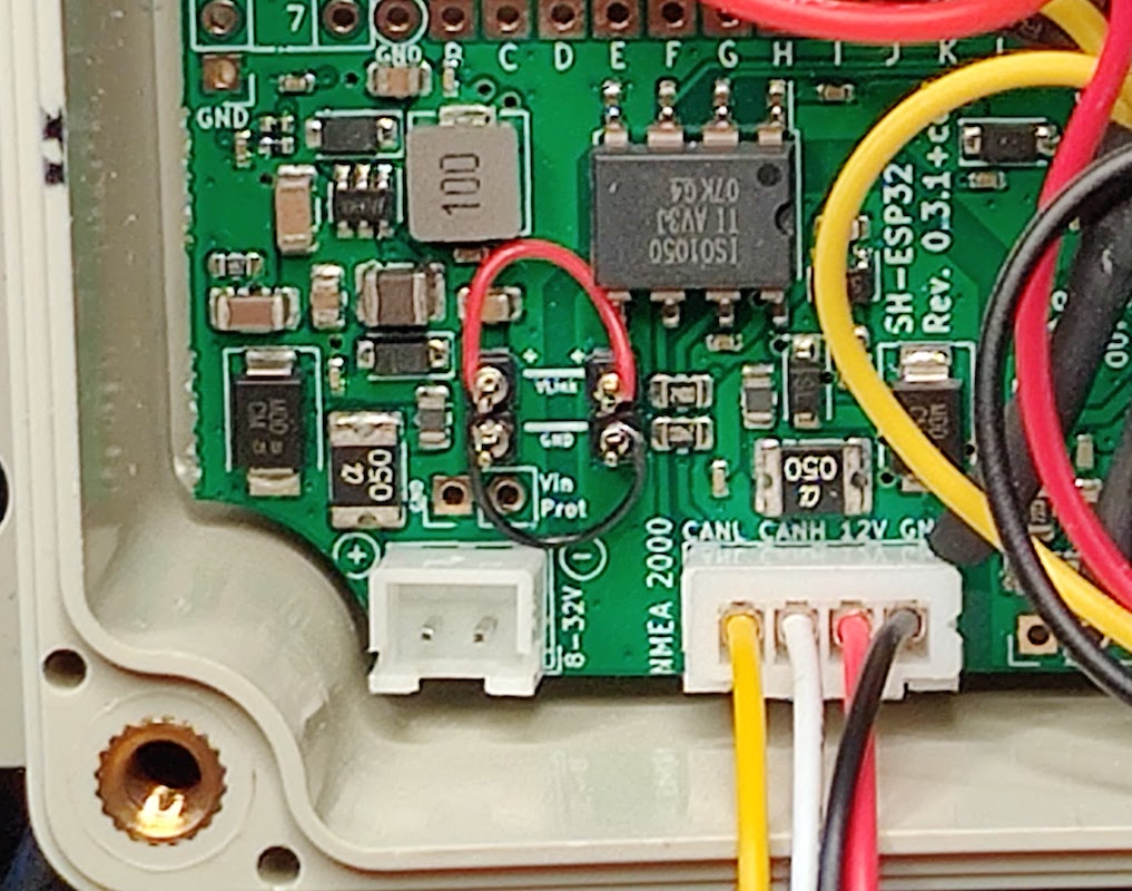
The wire link headers are normally unpopulated. Short the wire link plus and GND pins as indicated by the lines. Shorting can be done by soldering a short piece of wire directly on the headers, or as I did, by adding header pins and then connecting the pins using wire wrap. (I absolutely love wire wrap!)
Alternate wiring scheme
The crude mockup photo shows an alternate, and possibly better, wiring scheme for the 1-Wire connectors.
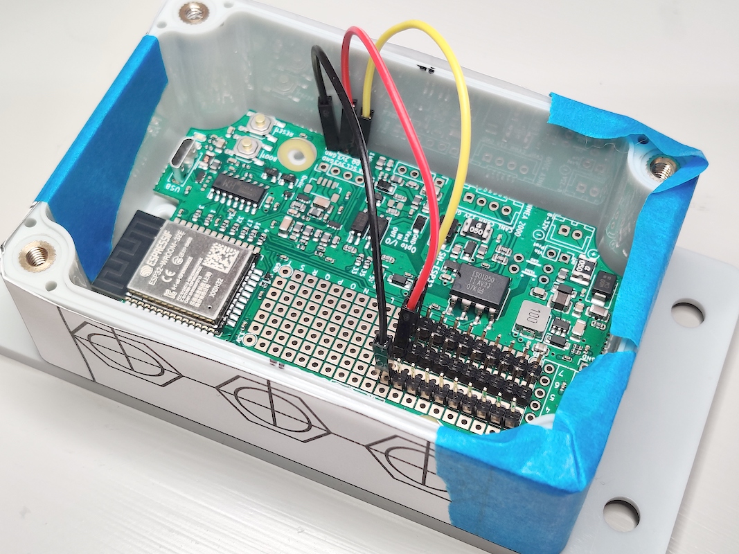
In this approach, you solder header strips on the SH-ESP32 proto area and short the pins of each row together on the bottom side of the board. The header strips form bus bars of sorts for each 1-Wire pin.
Assembly
Assuming that the 1-Wire data connectors are already in place, wiggle the SH-ESP32 board to the enclosure and fasten it with the small 3x6 mm screws. Then mount the power (or NMEA 2000) connector and connect everything to the board to the respective connectors.
If you're going to use an OLED display, now is the time to mount it.
My own end result is shown below.
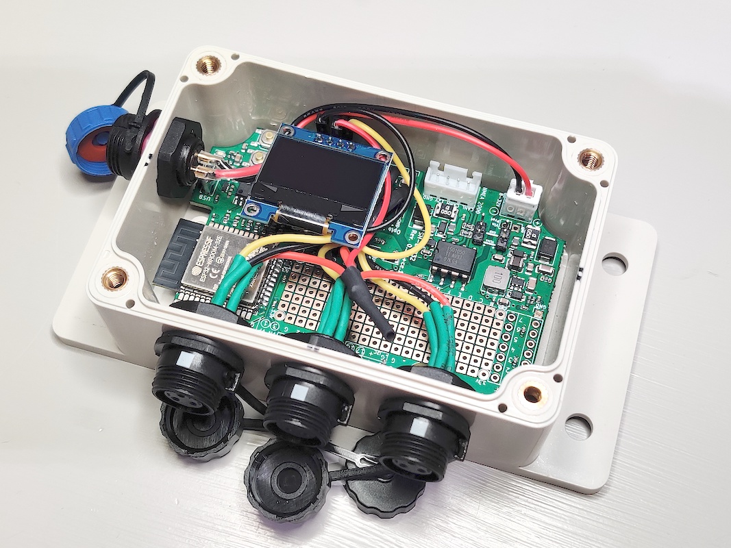
Final installation of the sensors on the engine itself is discussed later in this tutorial.
1-Wire network considerations
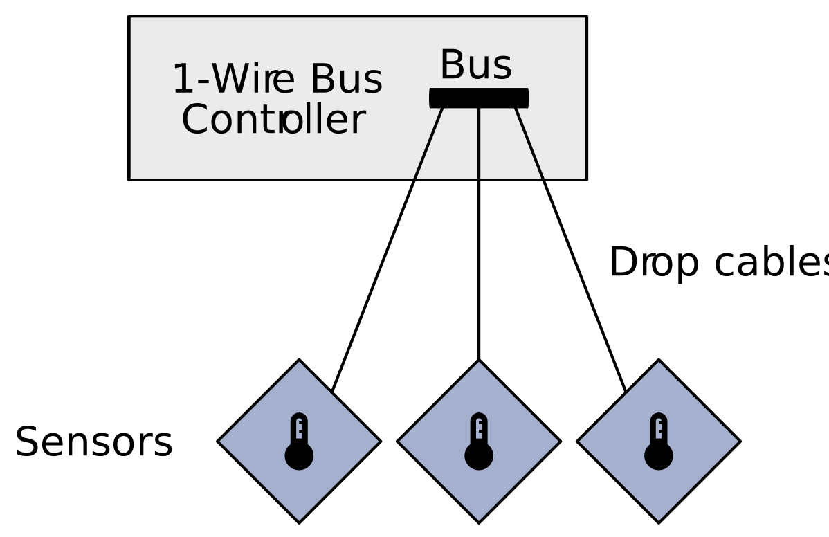
1-Wire is designed for a bus network topology, with client devices along a long bus cable:

The maximum bus length depends on the controller, cable used, and number of clients on the bus, but bus lengths over 100 m with 20 clients are quite realistic with dedicated hardware. The SH-ESP32 has not been designed with maximal network length in mind but at least 30 m bus lengths should be easily attainable with suitable cable.
The Springbok Digitronics 1-Wire Design Guide states that twisted pair is recommended for 1-Wire use. A regular Ethernet cable (Cat 5 or better) is well suited for long-distance 1-Wire installations. Springbok Digitronics even suggests a pinout standard for connecting 1-Wire devices with standard Ethernet RJ45 connectors. Having said this, 1-Wire is stated to work well even using flat telephone ribbon cable for distances of up to 30 m.
Individual sensors can be separated from the main bus by a length of drop cable (also known as stub cable). The maximum drop cable length recommended by Dallas Semiconductor is 3 meters.
In this tutorial, short bus distances are assumed -- actually, our bus is merely a single cable splice within the enclosure and the individual sensor cables are all drop cables. This works well as long as the drop cables aren't too long.
If you need to extend the network length, you should not extend the individual drop cables beyond the recommended three meters but extend the bus length instead.
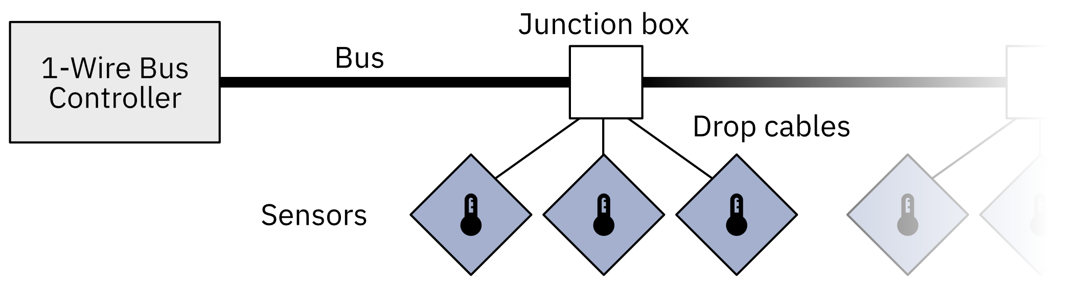
Place a junction box near the desired sensor locations, trim off extra drop cable length, and connect the sensors to the bus cable within the junction box. You can have multiple junction boxes along the bus.
Software
Prerequisites
Prerequisites are the same as for the NMEA 2000 gateway: you need to have Visual Studio Code and PlatformIO as well as drivers for the CH340 USB serial chip. Refer to that tutorial for installing them.
Downloading
Download the software from https://github.com/hatlabs/SH-ESP32-onewire-temperature. You can either clone the repo (if you're comfortable with Git) or download the source code as a zip file by clicking on the green "Code" button and selecting "Download ZIP". Unzip the package and open the directory in Visual Studio Code (File -> Open Workspace).
Code modifications
The example project assumes three sensors for engine oil, engine coolant, and engine wet exhaust temperature, respectively.
If you have a different number of sensors or are measuring different things, you need to modify the program.
Open the src/main.cpp file in Visual Studio Code.
The sensors are defined in main.cpp around line 97.
Modify the configuration paths and the variable names according to your liking.
Metadata for the sensor Signal K outputs are defined beginning from line 106. That defines the human-readable descriptions and value units for the Signal K paths.
The sensors are then connected to Signal K outputs around line 137. Again, you can modify the Signal K paths according to your preferences. It is advisable to try to follow the Signal K specification for the path names, but if you can't find anything fitting, feel free to invent your own.
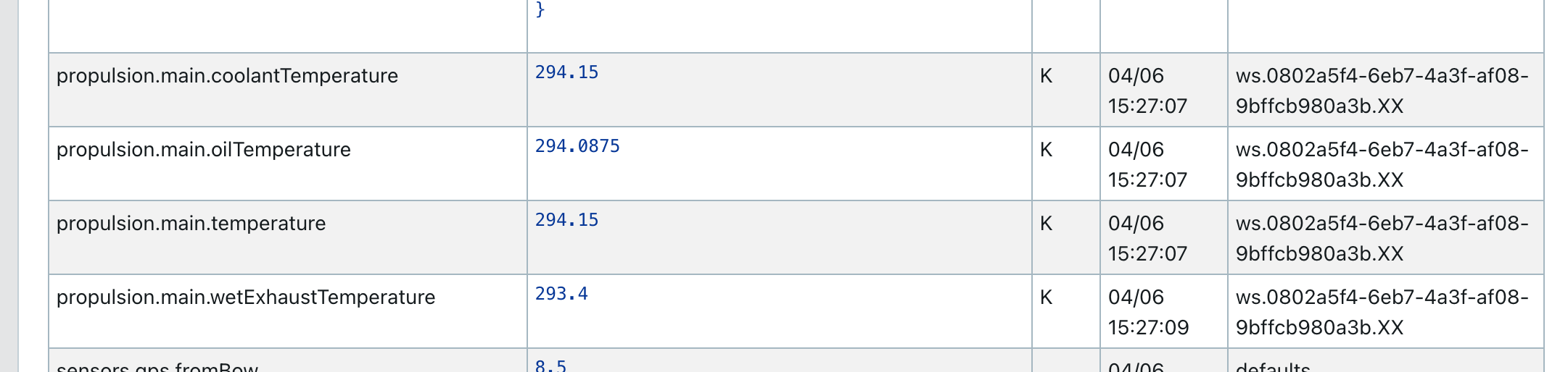
In the example, coolant temperature value is connected to two paths: propulsion.main.temperature and propulsion.main.coolantTemperature. Coolant temperature is typically regarded the overall engine temperature, but there is also a specific path defined for it. This slight redundancy guarantees that both paths are specified, should a downstream process expect either of them.
If you are using the OLED display, you want to modify the display outputs around line 170. Those define how the temperature values are displayed on the small OLED screen.
You might at this point be already wondering about the temperature units. Both Signal K and NMEA 2000 use Kelvins internally, and that is what SensESP uses as well. The idea is that everything is internally processed in standard SI units and conversion to customary units such as °C or °F is performed only when displaying the values. SensESP normally would never convert Kelvins to °C or °F, but displaying values on the OLED screen is that single big exception to the rule: the displayed values should be converted to customary units.
The tutorial software shows the temperatures by default in Celsius. If you want to have your temperatures in Fahrenheit, go back and modify the lines 29 and 30 accordingly.
NMEA 2000 data
Modifying the NMEA 2000 output is, due to the nature of the protocol, a somewhat more complex task. NMEA 2000 sends data in fixed-format messages. The message type is defined by its PGN (Parameter Group Number). Each PGN can contain one or more pieces of data. For example, PGN 130312 "Environmental Parameters" includes water temperature, outside ambient air temperature, and atmospheric pressure all in on message. In most PGNs, individual values can also be marked as undefined -- in the above example, if we only have air temperature, we can avoid sending bogus data by marking water temperature and atmospheric pressure as undefined.
One good source for PGNs and PGN structures is the canboat library PGN definition header file.
This can be cross-referenced with the NMEA 2000 message list of the NMEA 2000 library used to compile and transmit the messages.
Search the file for the PGN number or the data type you want to send and you'll likely find some information on the topic.
Generic temperature data is provided by PGNs 130310, 130311, 130312 and 130316. Engine temperature data is provided by PGN 127489 "Engine Parameters, Dynamic" and transmission data by PGN 127493 "Transmission Parameters, Dynamic".
In this tutorial, we're transmitting engine oil (sump) temperature, coolant temperature, and wet exhaust temperature. Some might be more interested in the actual exhaust gas temperature, but those go way above the capabilities of the 1-Wire sensors we're using and need to be measured with a specially fitted thermocouple probe. PGN 127489 transmits both oil temperature and coolant temperature, so we have to collect the values and send them together. The approach I took in this example is that the temperature values are stored in a variable, and whenever either oil or coolant temperature is updated, a PGN 127489 is always sent. The wet exhaust temperature is sent separately using PGN 130312.
To change the PGN mapping, you will have to modify the code around lines 62 and 219.
Sensor configuration
Each 1-Wire sensor contains a unique hardware address.
When the program first starts, it assigns newly detected sensor addresses to OneWireTemperature sensor objects and saves the information in the flash memory.
The device scan order is arbitrary, so if all sensors are connected at once, they are assigned to OneWireTemperature objects in a random order.
The assignments can be modified through the web configuration UI, but there's an easier way: connect the sensors one by one.
The example program defines OneWireTemperature objects in the following order: oil, coolant, exhaust. Hence, do this:
- Connect the sensor that will become the oil temperature sensor.
- Power on the device for a few seconds.
- Power off the device.
- Connect the coolant temperature sensor.
- Power on the device for a few seconds.
- Power off the device.
- Connect the exhaust temperature sensor.
- Power on the device.
- Done!
Following this approach guarantees that the sensors are registered in the correct order.
Testing
Test your device before installing it on the boat. If there are any issues with your setup, it's a lot easier to fix them before everything has been firmly attached in place.
Signal K
If you are using the device with Signal K, you need to connect it to your Signal K server. If you haven't set up one yet, follow the Signal K server installation instructions.
You could set the Wi-Fi and server information in the code, but this tutorial relies on automatic (Bonjour/mDNS/DNS-DD/Avahi) service discovery.
After powering up, if the device hasn't been configured yet, a wireless access point named "Configure temperatures" should appear. If you connect to it, you should be automatically taken to the WiFiManager configuration screen. If that doesn't happen, open the browser and navigate to http://192.168.4.1/. Select the Wi-Fi network you normally use and enter the password. The device should now automatically connect to the network.
Note: if you have set the Wifi settings once, there is at this moment not an easy way to change or reset those Wifi settings. You should use the PlatformIO's "Erase flash" command and upload the firmware again. This is being tracked as a future update.
If you have automatic service discovery correctly configured, you should immediately have a device access request appear on the Signal K server web UI:
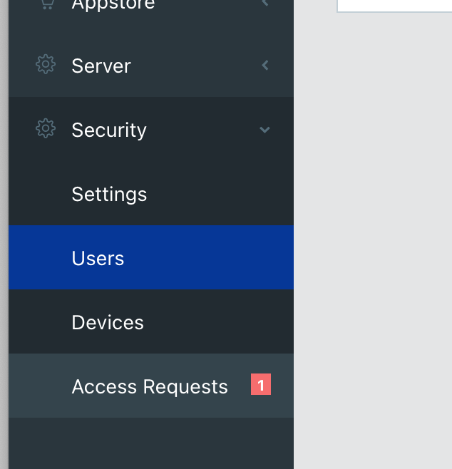
Open the access request, set authentication timeout to "NEVER", and click Approve. You should immediately get new data on the Signal K server dashboard and data browser.
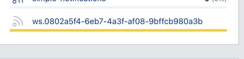
SensESP device on the dashboard:
Temperature readings on the data browser:
NMEA 2000
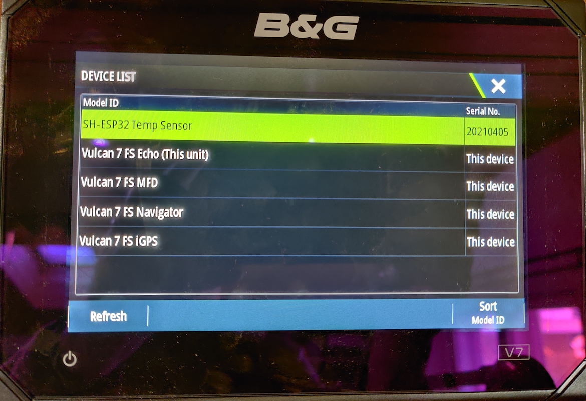
To test NMEA 2000 connectivity, plug your device into your NMEA 2000 network. Assuming you have a chart plotter on the network, you should be able to get the device list with the new temperature sensor on it:
If the SH-ESP32 device data is inspected, it should show three different temperature values:
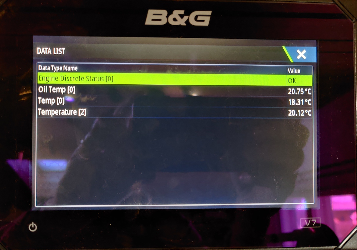
This verifies that the connection is working.
Sensor installation on boat
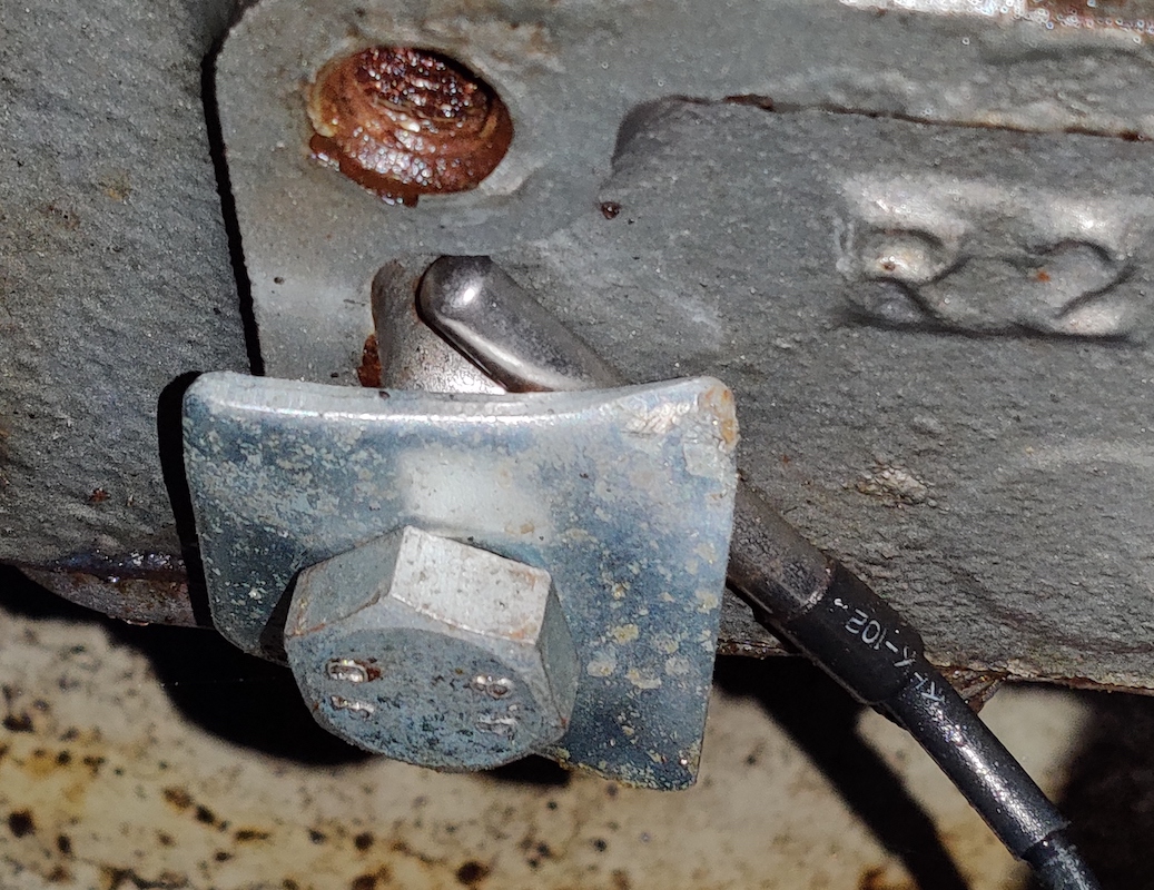
All that remains is to install the device and the sensor cables on the boat. I didn't want to do permanent modifications to my Yanmar 3GM30F diesel engine. My sensor installation was very much a low-tech one, but nevertheless quite functional. The oil temperature sensor went to the side of the engine oil pan. There was a threaded bolt hole on the oil pan. I took a suitably sized square washer and bent one corner slightly, then used that to secure the sensor against the oil pan. When doing this, take care to not tighten the bolt too hard, as that will likely crush the sensor.
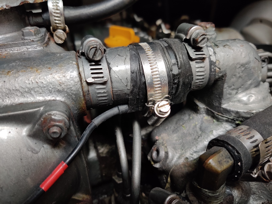
The coolant temperature is measured on the surface of the coolant return hose. The sensor is first taped on with silicone tape. Silicone tape can sustain high temperatures, is a very good insulator, and is self fusing, providing a secure seal around the hose and the sensor. Nevertheless, I would still add a hose clamp over the tape to ensure that the cable can't get loose and fall onto the engine belts.
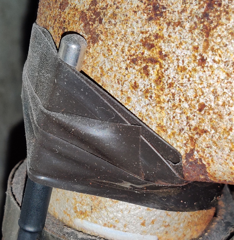
The exhaust sensor went onto the exhaust bend, after the coolant water hose connection. Similar to the coolant temperature sensor, I attached it with silicone tape and a hose clamp.
For all sensors, take care to route the cables neatly. There should be some slack to allow for engine vibrations, but otherwise the cables should be mounted on some fixtures every 30 cm (1 ft) or so. At no point should the cable be able to chafe against the vibrating engine. Also, be careful not to allow the cable touch very hot parts of the engine such as the exhaust manifold.
Congratulations! You now have a fancy new temperature sensor for your engine, and skills to build other sensors as well! Time to go brag online and to your marina neighbors!
Add-on Hardware
Add-on hardware
This page lists add-on boards developed for the SH-ESP32.
Engine Top Hat
SH-ESP32 Engine Top Hat
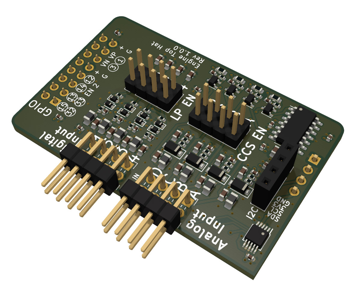
SH-ESP32 Engine Top Hat (Engine Hat) is an add-on board for the SH-ESP32. It allows you to measure common engine outputs:
- Tachometer (RPM) senders, either using dedicated tach senders or alternator W terminals
- Digital inputs such as engine alarms
- Tank senders
- Other resistive senders such as oil pressure senders with a resistance range of 0-300 ohm
The Engine Hat is a developer device. While example software is provided online, using the Engine Hat requires basic familiarity with working with sensors and microcontrollers.
See the Getting Started page for hardware installation and connection instructions.
The Hardware page contains more detailed information about the Engine Hat hardware.
The SH-ESP32 Engine Top Hat is open hardware and the design files can be found at the project GitHub repository. The product is available for purchase at hatlabs.fi.
Specifications
- Compatible with SH-ESP32 (all versions)
- 4 digital input channels (1-4)
- input voltage range: -30V to +30V
- threshold voltage: 1.65V
- optional 1st order low-pass filter with cutoff frequency of 2.3 kHz
- 4 analog input channels (A-D)
- input voltage range: 0-29V
- analog-to-digital converter: AD1115
- ADC resolution: 16-bit
- optional constant-current source with 10 mA current
- resistance measurement range: 0-300 ohm
Getting Started with the SH-ESP32 Engine Top Hat
Hardware Installation
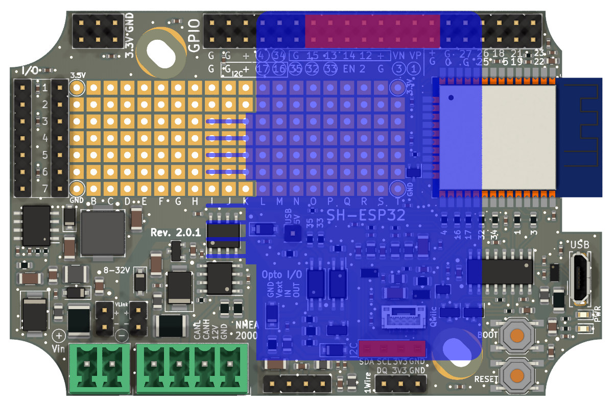
The Engine Hat is intended to be used with the SH-ESP32. To install the Engine Hat, align it with the I2C and GPIO connectors on the SH-ESP32 and press down until the header pins have fully mated. See the pictures below for the exact alignment.
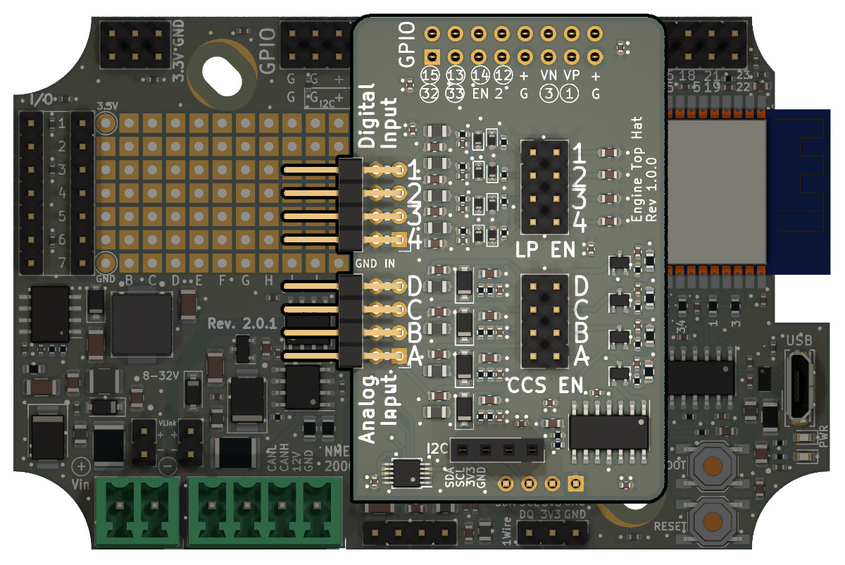
Outline of the engine hat in blue, with the mating connectors highlighted in red:
Connecting Tank Senders and Other Resistive Sensors
The analog and digital inputs are on the stacked horizontal headers of the board. The inputs are on the top row while the bottom row is connected to ground.
Resistive sensors are transducers or electromechanical devices that convert a mechanical, temperature, pressure, or other signal to electrical resistance. As such, they are passive devices and do not generate electricity. In short, resistive sensors can be thought of as fancy potentiometers, or adjustable resistors.
The Engine Hat implements a constant current source to measure resistance values. A 10 mA current is sent through an analog input pin, and the voltage between the pin and ground is measured. Resistance values from close to 0 ohm to about 300 ohm can be measured. This range covers both typical European (0-180 ohms) and American (240-33 ohms) tank senders as well as common oil pressure sensors.
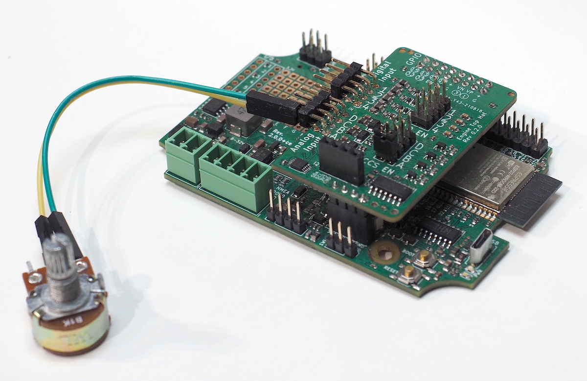
To connect the sender, attach the sender measurement pin to the top pin of an analog input channel. The sender ground pin is connected to the bottom pin.
The photo below illustrates connecting a potentiometer to the Engine Hat.
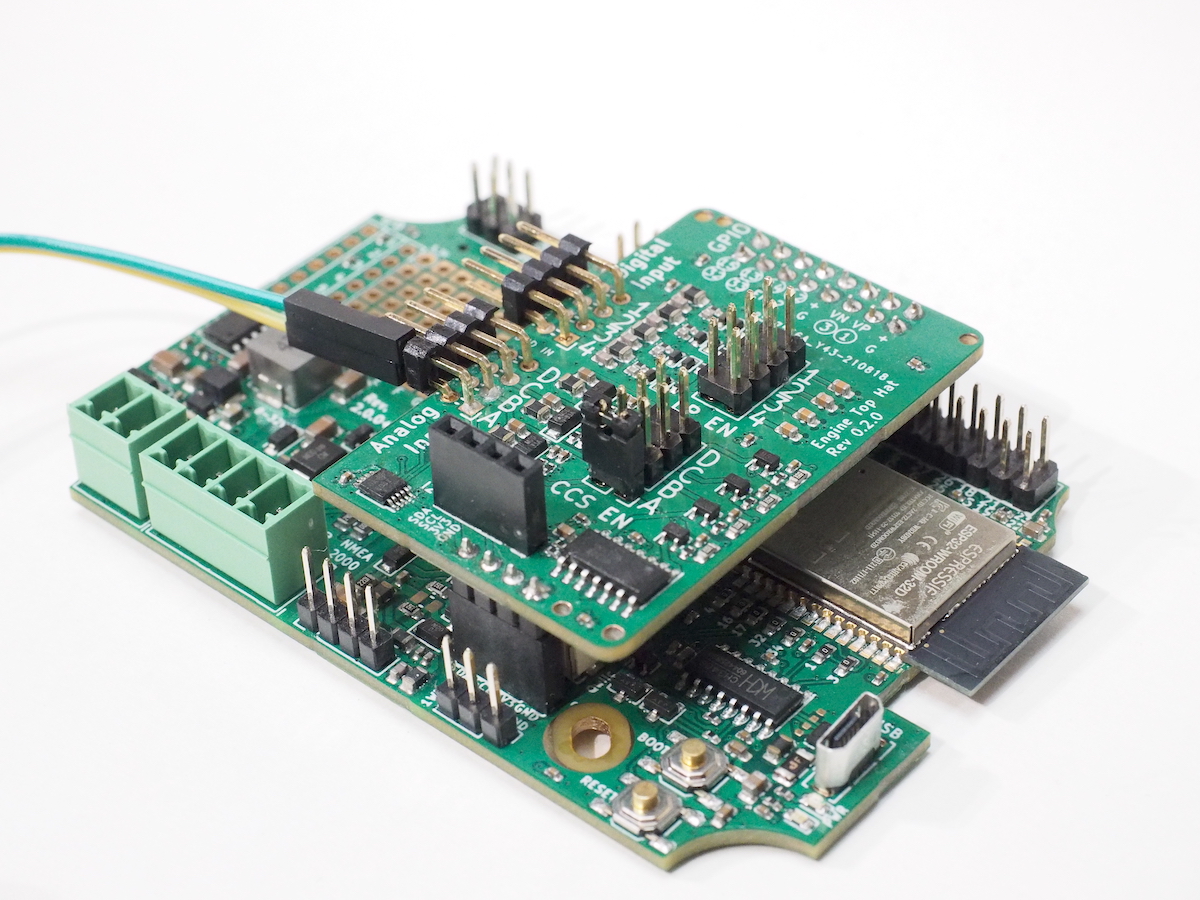
By default, the analog inputs are configured as passive voltage sensors. The constant current source on the analog inputs must be separately enabled by connecting a jumper over the respective row of the CCS header, as shown in the photo below:
Connecting Tank Senders with Existing Gauges
If you want to keep an existing fuel tank gauge connected, you can safely connect the Engine Hat in parallel to it. However, in this case the original gauge will provide the measurement current, and you must not enable the constant current source. In this case the engine hat will perform a simple voltage measurement.
Measuring Voltages
The Engine Hat analog inputs can be used for passive voltage measurements as well. The measurement range is 0-29V.
Connect the measurement voltage in a similar manner as a tank sender described above, but leave the constant current source disabled. Pay attention to polarity! Reverse polarity may cause damage to the device.
Connecting Alarms and Other Binary Outputs
Digital inputs can be used for detecting engine alarms and other similar signals. Connect them to the Digital Input header, with the hot lead going to the top row and ground to the bottom. The inputs support a voltage range of 0-30V, with a fixed threshold voltage of 1.65V for the logic level change. Negative voltages are allowed.
Connecting Tachometers (RPM senders)
The digital inputs can be used to measure tachometer RPMs or other repetitive pulse measurements such as fuel flow meters. Connect them like alarms, with the hot lead going to the top row and ground to the bottom. Both alternator W terminals and inductive tachometer senders such as the ones used on Yanmar engines can be directly connected.
NOTE: If you are measuring RPM using an alternator W terminal, you might be better off leaving the GND wire unconnected. When charging, the alternator GND is likely to be at a different voltage than the battery negative terminal (your boat's typical reference GND). Connecting a negative signal wire from the alternator to the GND pin on the engine hat would likely cause a ground loop: current flowing on the GND wire due to the voltage difference, causing possibly a lot of low-frequency noise.
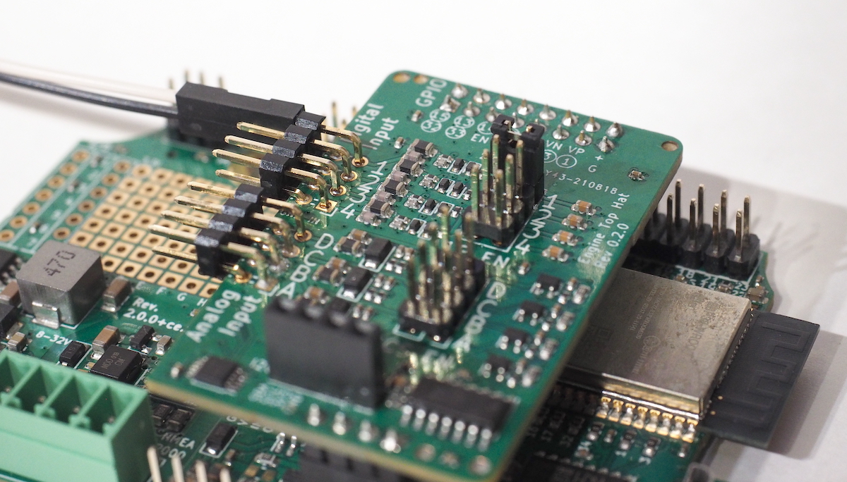
Some tachometer senders such as the alternator W terminals are notoriously noisy, resulting in unreliable measurements. In such cases, the reported RPM value usually is much higher than the actual RPM. The Engine Hat includes an optional low-pass filter with a 2.3 kHz cutoff frequency to help filter out such noise. To enable the low-pass filter for a digital input channel, connect a jumper over the respective row of the LP EN header:
Note that the hardware filter only will get you so far. For particularly noisy input signals, implementing additional software filtering may be required for reliable results.
Software
See the SH-ESP32-engine-hat-firmware GitHub repository for example firmware.
SH-ESP32 Engine Top Hat Hardware
Analog Inputs
The Engine Hat includes four analog input channels, implemented using Texas Instruments' AD1115 analog to digital converter. The analog inputs can be individually configured as passive voltage sensors or active resistance sensors. As voltage sensors the input channels sense a 0-29V voltage range with a 16-bit resolution. As resistance sensors, they implement a 10 mA constant-current source to read sensor resistances between 0-300 ohm.
Digital Inputs
Engine Hat has four wide voltage range digital inputs. The inputs support an input voltage range of 0-30V. The threshold voltage is fixed at approximately 1.65V.
The digital inputs can be used either as digital value inputs for detecting engine alarms or other similar signals, or as counters for measuring tachometer signals or other repetitive pulses.
Each digital input channel has an optional, jumper-enabled low-pass filter with a 2.3 kHz cutoff frequency. The low-pass filter can be used to filter noisy tach signals, in particular, the alternator W terminal signals.
Tour Around the Board
The illustration below shows the two main functional blocks of the Engine Hat.
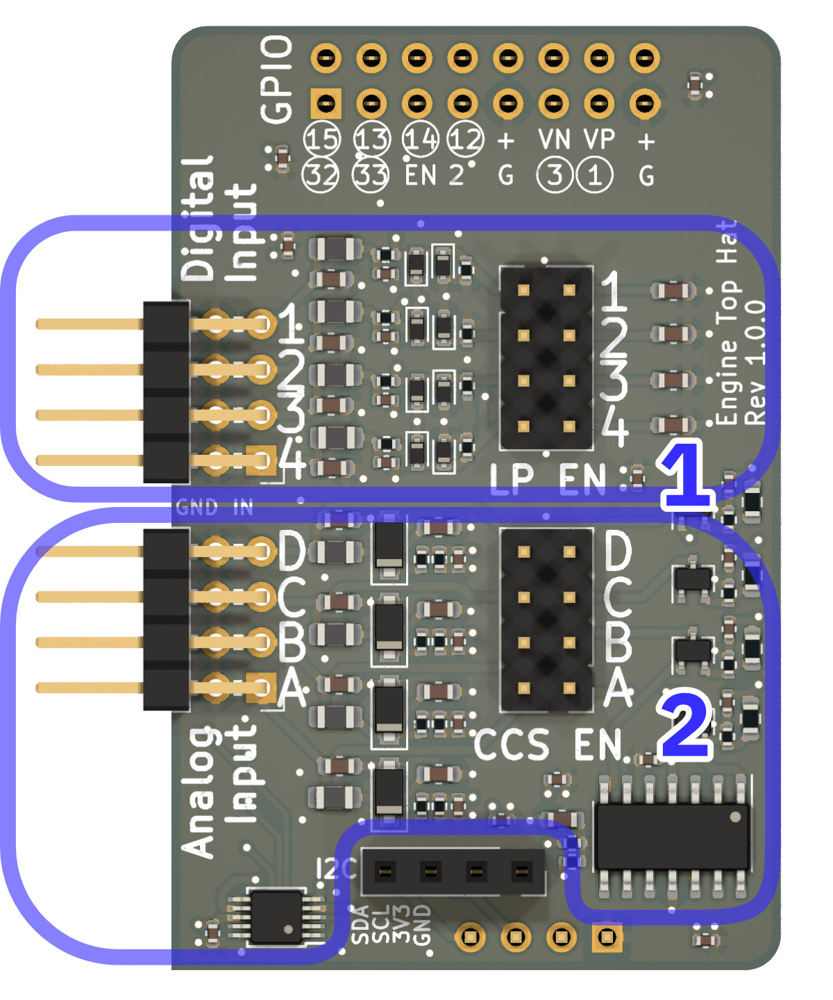
Block 1 provides the digital input functionality for alarm inputs and frequency counting.
Block 2 provides the four analog input channels, their input protection, and the optional constant-current source.
Connectors
The Engine Hat connectors are shown below.
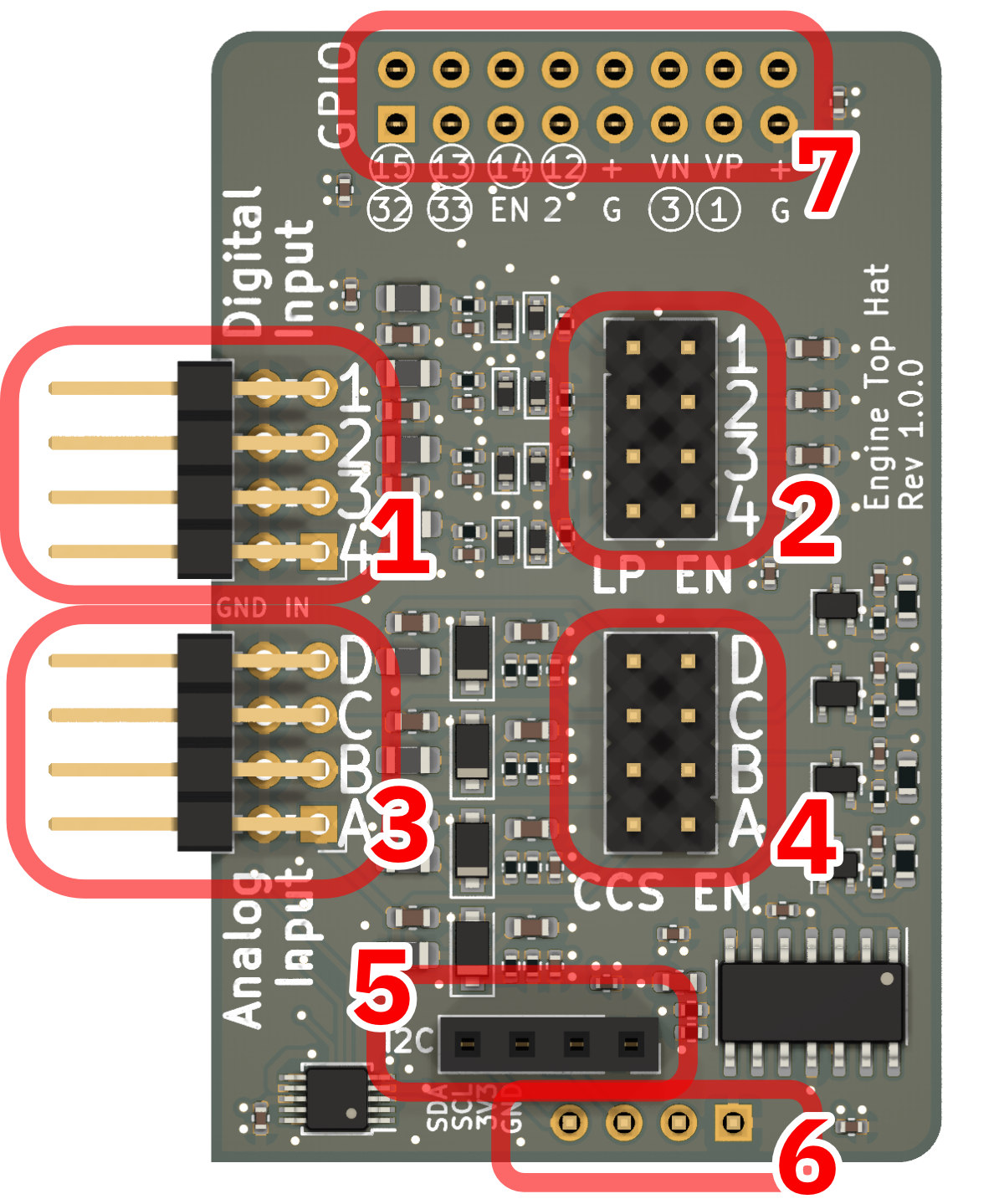
- Stacked horizontal header for the four digital inputs. The top row is for the digital input signal pins, the bottom row is for the ground connections.
- Jumper header for enabling the low-pass filter for each input channel.
- Stacked horizontal header for the four analog input channels. The top row is for the analog input signal pins, the bottom row is for the ground connections.
- Jumper header for enabling the constant-current source for each analog input channel.
- I2C pass-through female header for connecting a display module or other I2C devices.
- I2C male header for connecting to the main board (on the bottom side of the PCB).
- GPIO female header for connecting the digital inputs to the main board (on the bottom side).
Pinout
The sections below documents how the inputs are mapped to the ESP32 GPIO pins.
Digital inputs
| Input # | ESP32 GPIO |
|---|---|
| 1 | 15 |
| 2 | 13 |
| 3 | 14 |
| 4 | 12 |
Analog inputs
Analog inputs are read using the ADS1115 analog-to-digital converter.
The raw input signal is scaled using a voltage divider down to voltage levels accepted by the ADC. The scaling factor is 2.048/29.
The ADS1115 uses the I2C bus for communicating with the ESP32. The default I2C address is 0x4b, but that can be changed using the solder jumper pads on the bottom side of the PCB.
Note that the SH-ESP32 uses GPIO 16 for the I2C SDA line and GPIO 17 for the I2C SCL line. These values are different from the Arduino ESP32 framework defaults, and any generic example code should be adjusted accordingly.
Design Files and Schematics
SH-ESP32 Engine Top Hap design files can be found at the project GitHub repository.
Schematics for different hardware revisions can be found here:
Appendices
Hardware revisions
Introduction
This page documents different board revisions and provides links to the schematics. Full design file history is available at the SH-ESP32-hardware GitHub repository.
Version 0.3.1
First version sold at hatlabs.fi.
Schematics: SH-ESP32-0.3.1-schema.pdf
Version 1.0.0
Changes to 0.3.1:
- Move bypass capacitors further away from the mounting holes
- Fix the erroneous solder jumper silkscreens for GPIOs 1 and 3
- Improve the silkscreen for the 2x3 power connector header
- Change some components according to component availability
Schematics: SH-ESP32-1.0.0-schema.pdf
Version 2.0.0
Changes to 1.0.0:
- Change the power input buck converter to XL1509 for easier part availability
- Instead of the ISO1050 isolated CAN transceiver, use a separate digital isolator and transceiver
- Use Phoenix MC type 3.81 mm pluggable screw terminals for power input and CAN bus connectors. These connectors are mechanically more durable and easier to use than the JST XH type connectors used earlier.
- Connectors and headers are now pre-soldered to the board
Schematics: SH-ESP32-2.0.0-schema.pdf
Version 2.0.1
- Minor part changes to improve part availability
Schematics: SH-ESP32-2.0.1-schema.pdf
Version 2.0.2
- Minor ESD protection improvements
- Minor part changes according to manufacturer part availability
Version 2.0.3
- Minor part changes according to manufacturer part availability
Schematics: SH-ESP32-2.0.3-schema.pdf
Errata
This page lists all known hardware bugs for different SH-ESP32 revisions.
Silkscreen issues
Solder jumper labels for GPIOs 1 and 3
The silkscreen markings for the bottom side solder jumpers for GPIO pins 1 and 3 are incorrect. The solder jumpers for the TXD0 and RXD0 pins used for USB serial communication are labeled 3 and 34 but should be 1 and 3 instead.
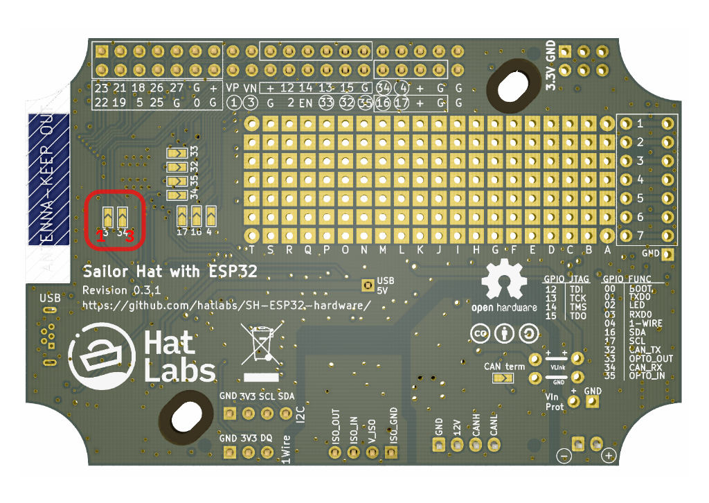
Affects boards up to revision 0.3.1.
Media assets
Here you can find some high-resolution photos and other pictures suited for publication use.
Renderings
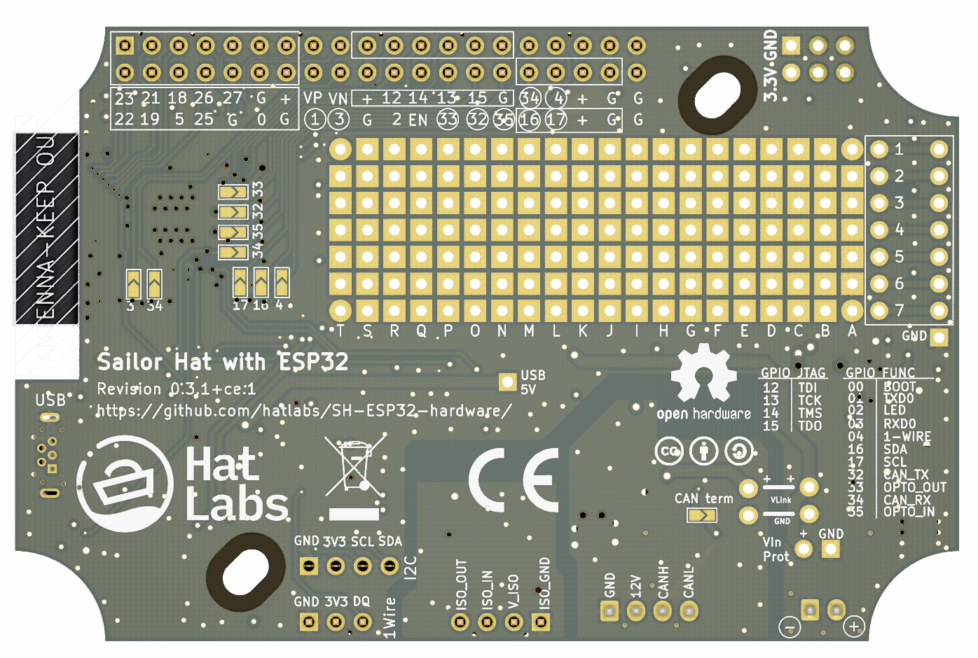
SH-ESP32 rendering, top:
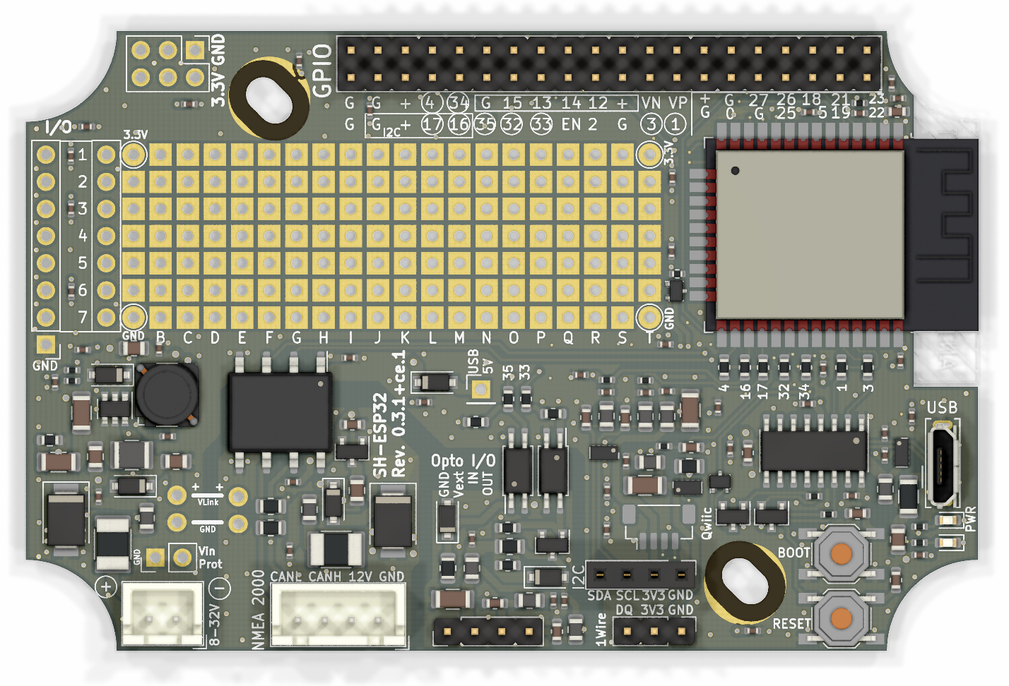
SH-ESP32 rendering, bottom:
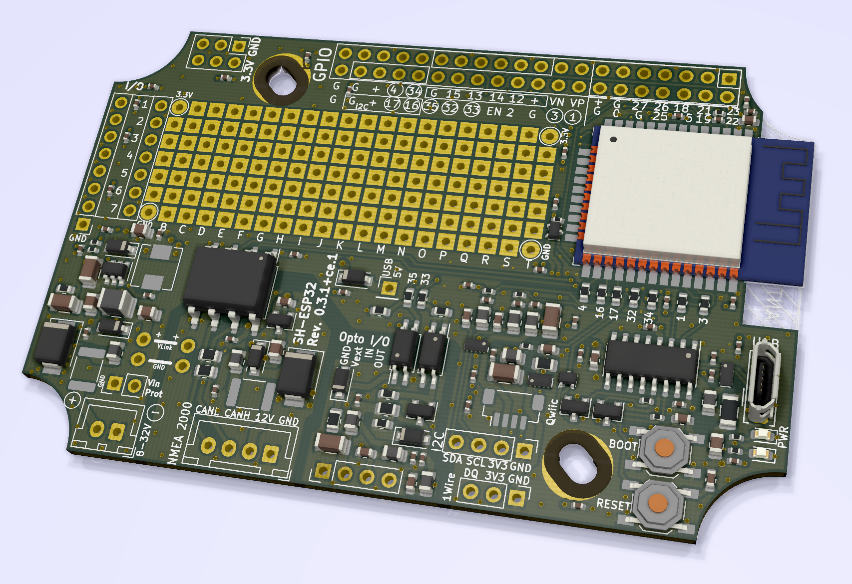
SH-ESP32 rendering, top, non-orthogonal:
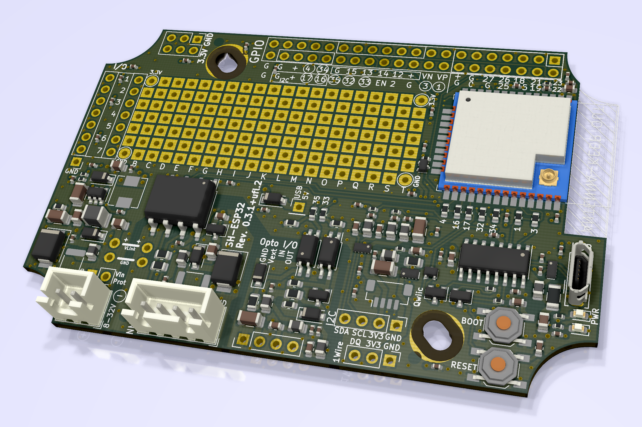
SH-ESP32-ufl (external Wi-Fi antenna version) rendering, top, non-orthogonal:
Photos
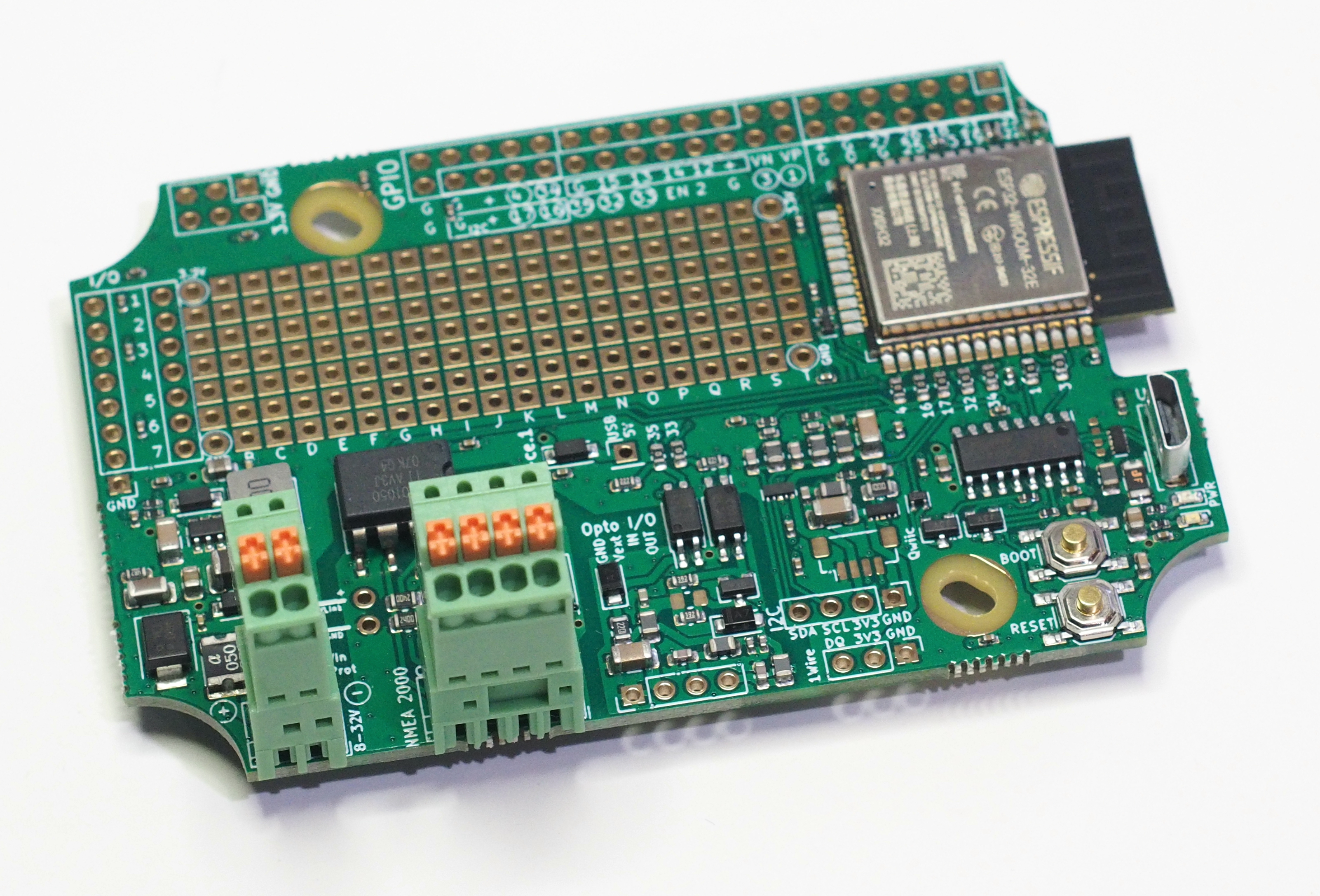
SH-ESP32 board with pluggable terminal blocks:
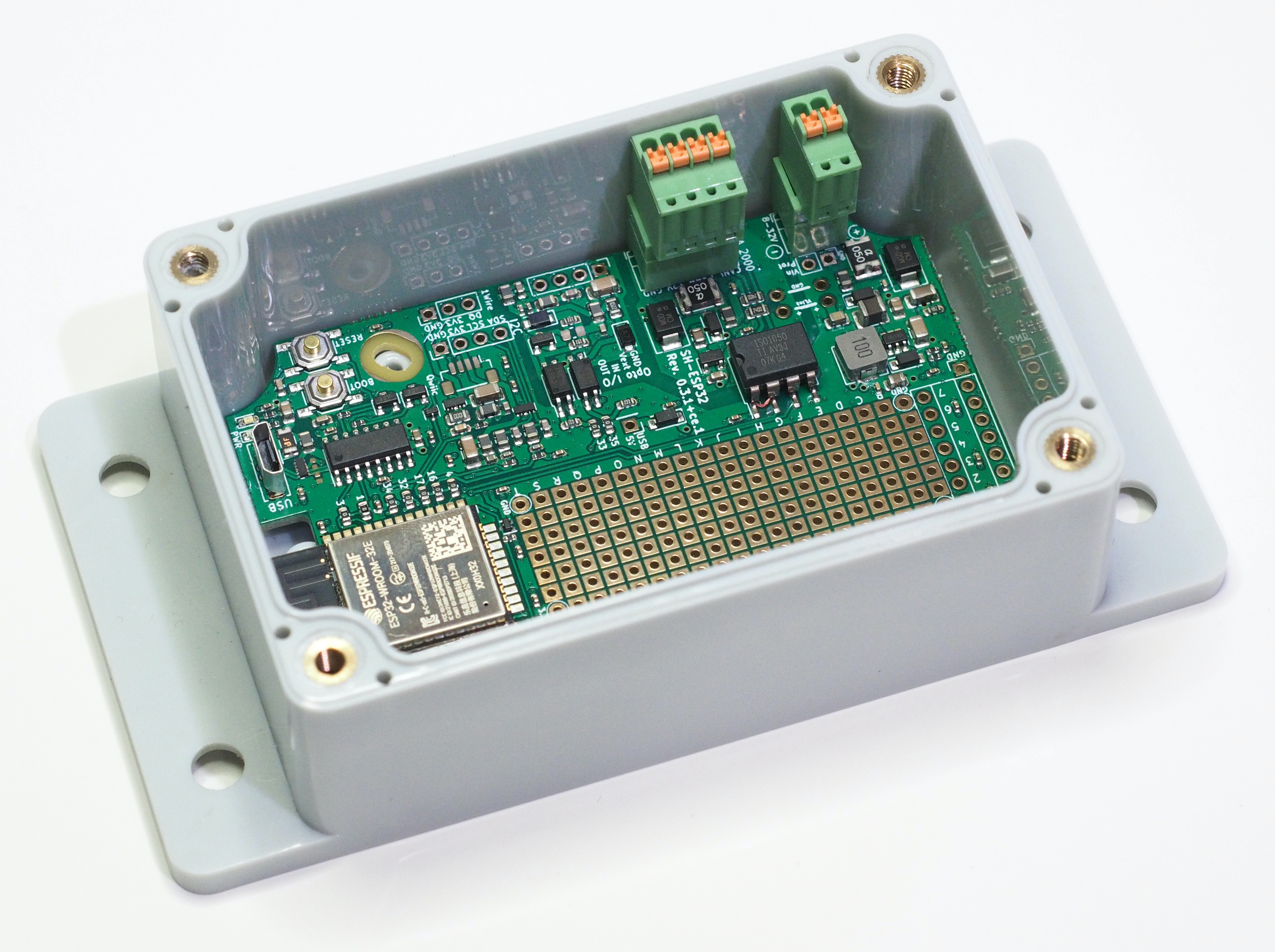
SH-ESP32 in an enclosure:
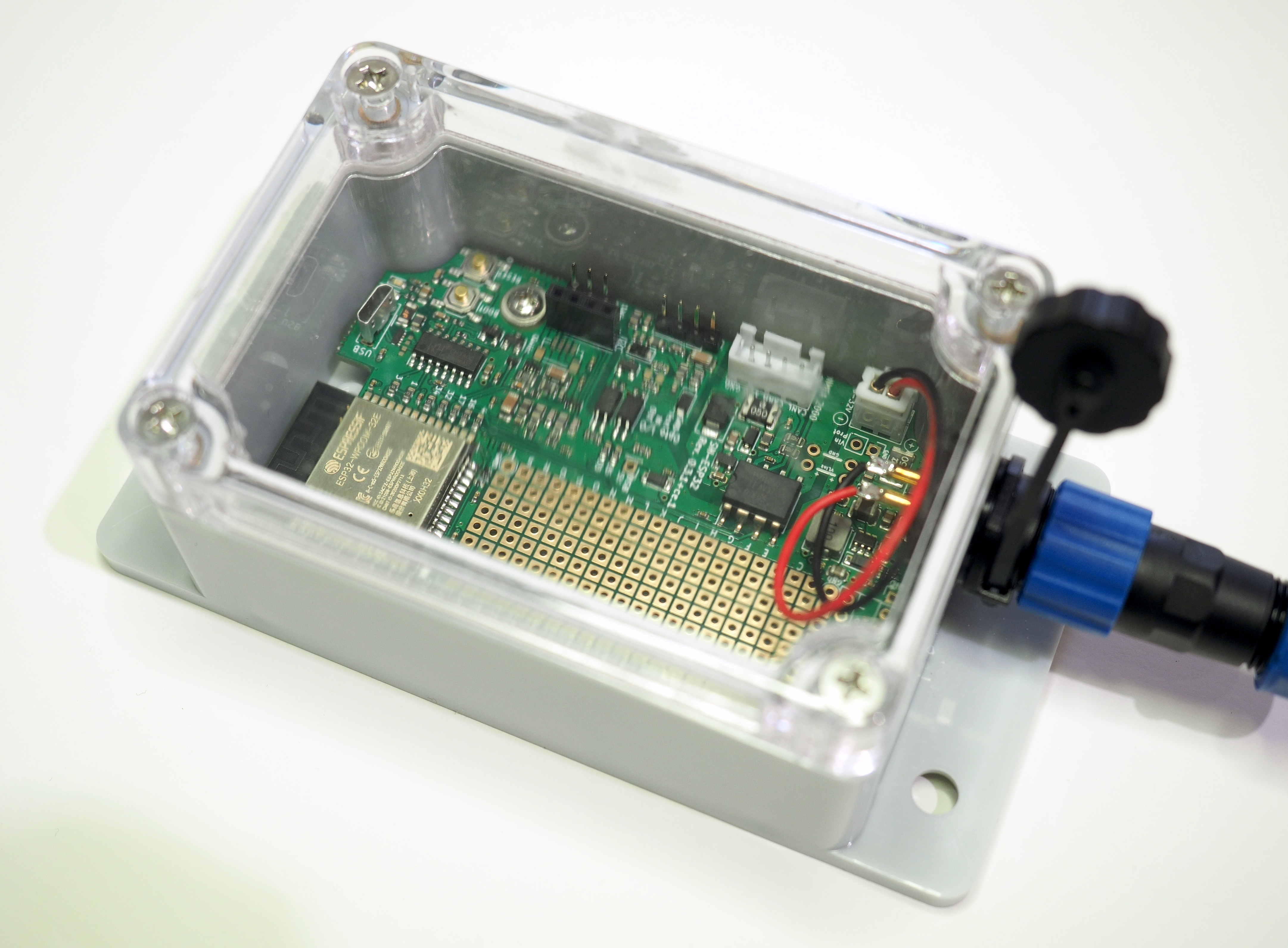
SH-ESP32 in an enclosure with the power plug:
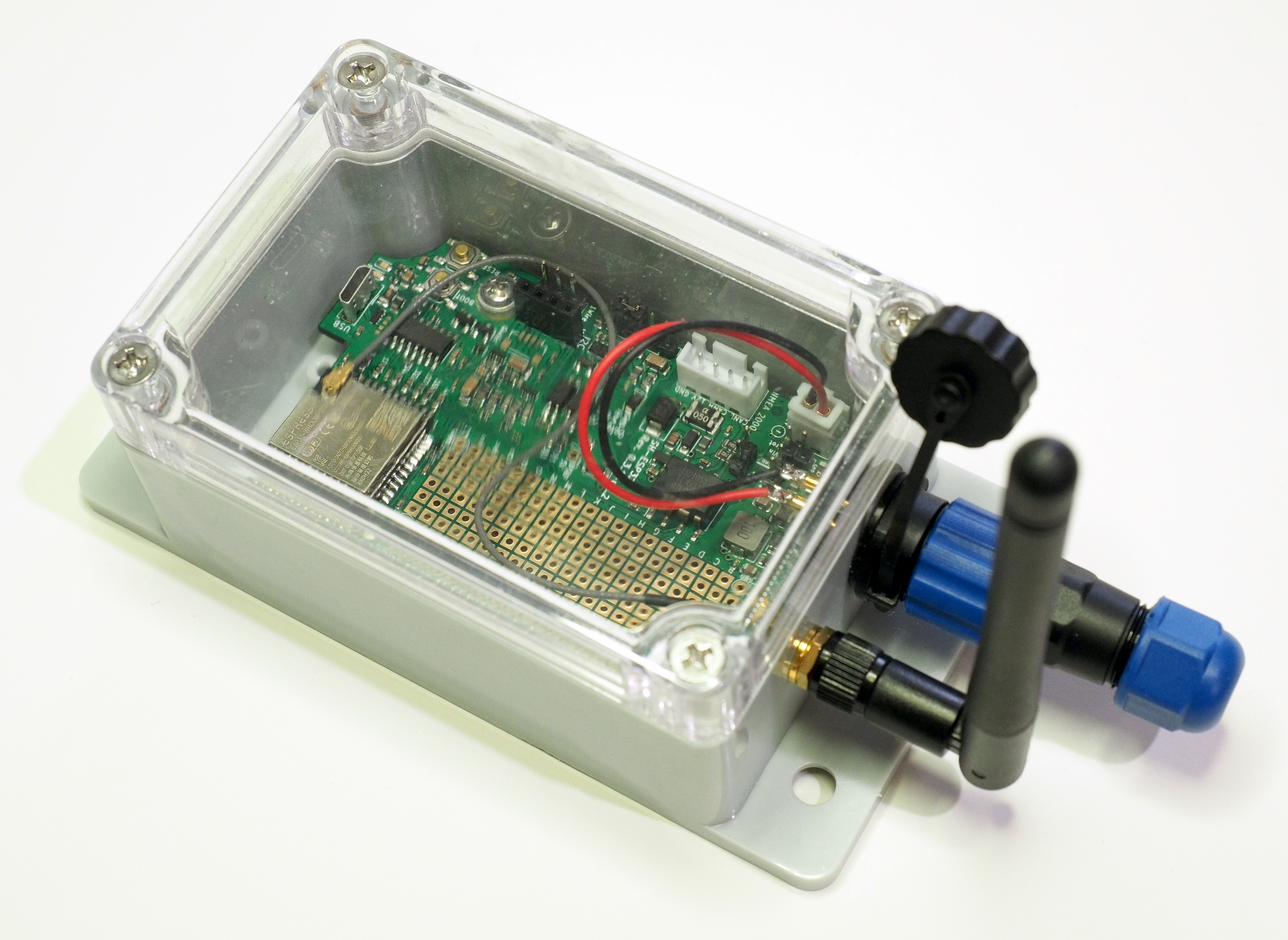
SH-ESP32-ufl in enclosure:
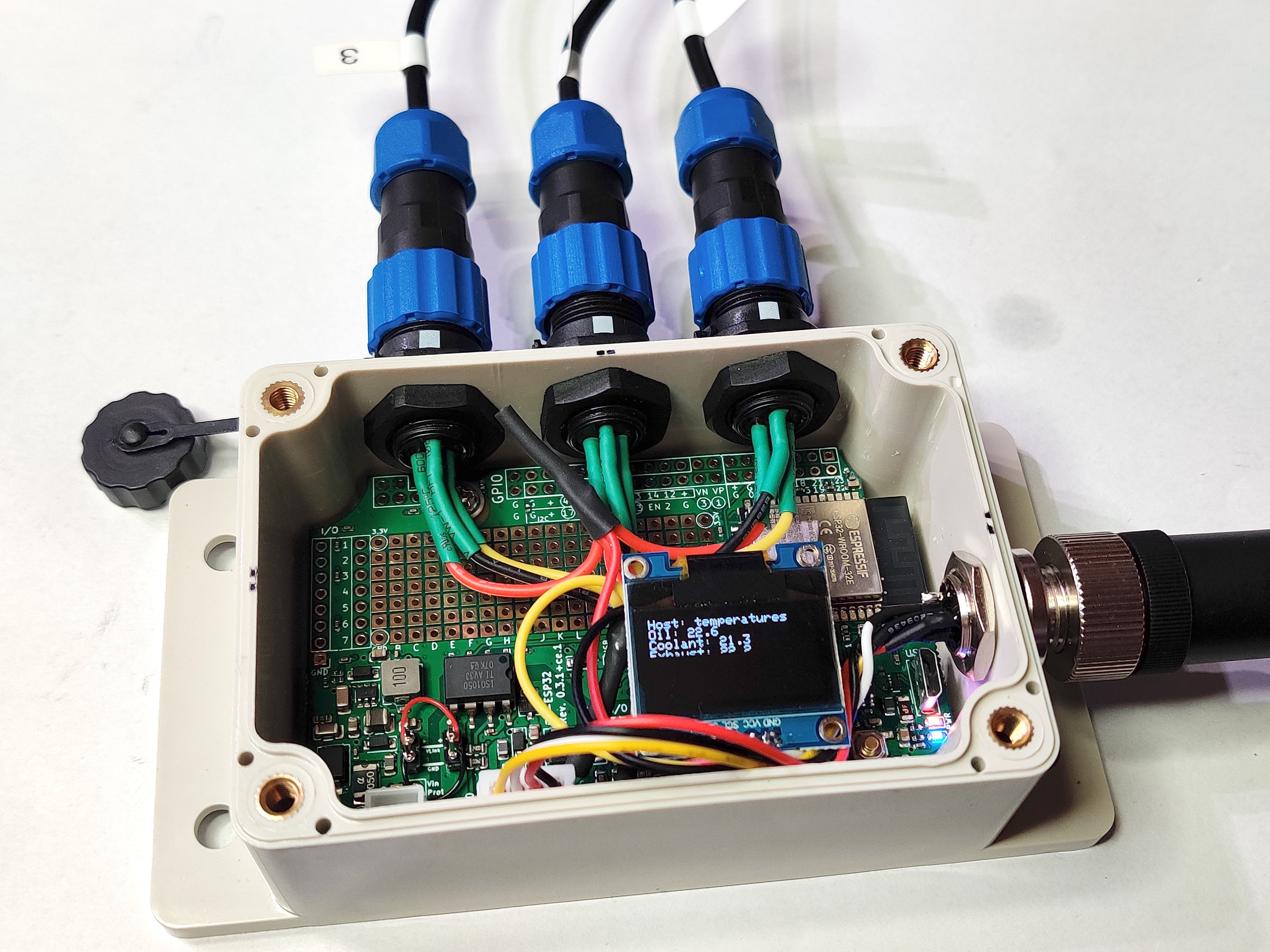
SH-ESP32 with 1-Wire temperature sensors:
SH-ESP32 NMEA 2000 gateway finished assembly:
Acknowledgments
Matti Airas, the Mad Hatter and founder of Hat Labs Ltd, initiated the project and has done most of the initial hardware development and testing. Mark Farnan has done major contributions and hardware design improvements, including all add-on board designs. Karl-Erik Gustafsson has provided a lot of invaluable guidance, especially regarding electromagnetic compatibility design.