Introduction
HALPI2 is a ready-to-use boat computer based on the Raspberry Pi Compute Module 5 (CM5). It offers a comprehensive set of features well suited for marine, automotive, and many industrial applications.

🔗 Shop Link
Purchase HALPI2 from the Hatlabs web shop.
What is HALPI2?
HALPI2 represents the latest evolution in rugged embedded computing, combining the power and ecosystem of Raspberry Pi with specialized features for demanding environments. Unlike standard single-board computers, HALPI2 is engineered from the ground up for 24/7 operation in harsh conditions where reliability is paramount.
The system integrates a Raspberry Pi Compute Module 5 with a custom carrier board, all housed in a waterproof aluminum enclosure that doubles as a heat sink. This design provides the computational power needed for modern applications while maintaining the robustness required for marine and industrial use.
Key Features and Capabilities
Enclosure Features
- Waterproof (IP65) aluminum enclosure, size 200×130×60 mm
- Standard connectors for power, NMEA 2000, gigabit ethernet, HDMI, 2× USB 3.0, and WiFi/Bluetooth antenna
- Flexible connectivity with options for 3× PG7 cable glands or SP13 waterproof connectors
- External antenna support via cutouts for 2 extra SMA connectors
- Wall-mount design with connectors positioned for easy installation
Hardware Features
- Wide input voltage range from 10 to 32 VDC with protection up to 100 VDC
- Intelligent current limiting: max input current 0.9 or 2.5 A, user-selectable
- Dual power options: 12V/24V direct connection or 12V NMEA 2000 bus power
- Super-capacitor backup for glitch immunity and graceful shutdown during power loss
- Advanced power management with automatic power loss detection
- Passive cooling design with CM5 in direct contact with enclosure
- High-speed storage via standard M.2 NVMe SSD interface
- Expansion capability through standard Raspberry Pi 40-pin GPIO header
- Rich I/O options: 2× HDMI, 2× MIPI (DSI/CSI), 4× USB 3.0, gigabit ethernet
- Marine-specific interfaces: CAN FD (NMEA 2000) and RS-485 (NMEA 0183)
- Real-time clock with backup battery for accurate timekeeping
- Visual status indication via five RGB LEDs
- User interaction through configurable button headers
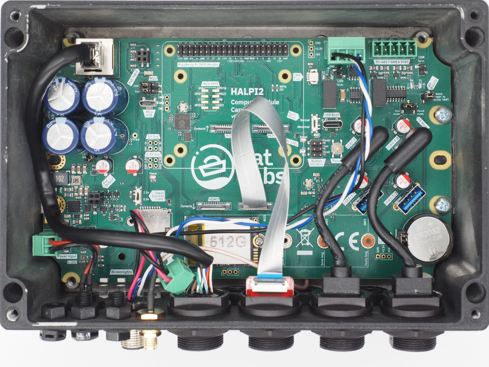 Interior view of the HALPI2 showing the carrier board and different connectors.
Software Features
- Pre-configured operating system images available for immediate deployment: OpenPlotter, Raspberry Pi OS and Raspberry Pi OS Lite
- Comprehensive monitoring of voltage, current, and temperature
- Transparent firmware updates over I2C interface
Target Applications
Marine Applications
- Navigation systems with Chart plotters and GPS integration
- Data logging for engine parameters, environmental sensors, and vessel performance
- Signal K servers for unified boat data management
- General-purpose onboard computing for internet access and communication
- NMEA 2000 network debugging for improved system reliability
Industrial Applications
- Process monitoring and control systems
- Environmental sensing and data acquisition
- Remote monitoring stations
- Equipment automation and control
- Predictive maintenance systems
Automotive Applications
- Fleet management systems
- Telematics and vehicle tracking
- In-vehicle infotainment systems
- Diagnostic and monitoring platforms
What's in the Box
Your HALPI2 package includes:
- HALPI2 unit with pre-installed Compute Module 5 and NVMe SSD (unless ordered without)
- Power cable with E7T connector (Amphenol LTW Ceres Mini compatible), length 2 m
- E7T cable plug for custom installations
- DC barrel connector pair (5.5 x 2.1 mm) for use with standard 12V/24V power supplies
- Raspberry Pi Antenna for WiFi and Bluetooth connectivity
- 3 pcs PG7 cable glands for additional interfaces
- Quick start guide and warranty documentation for getting started
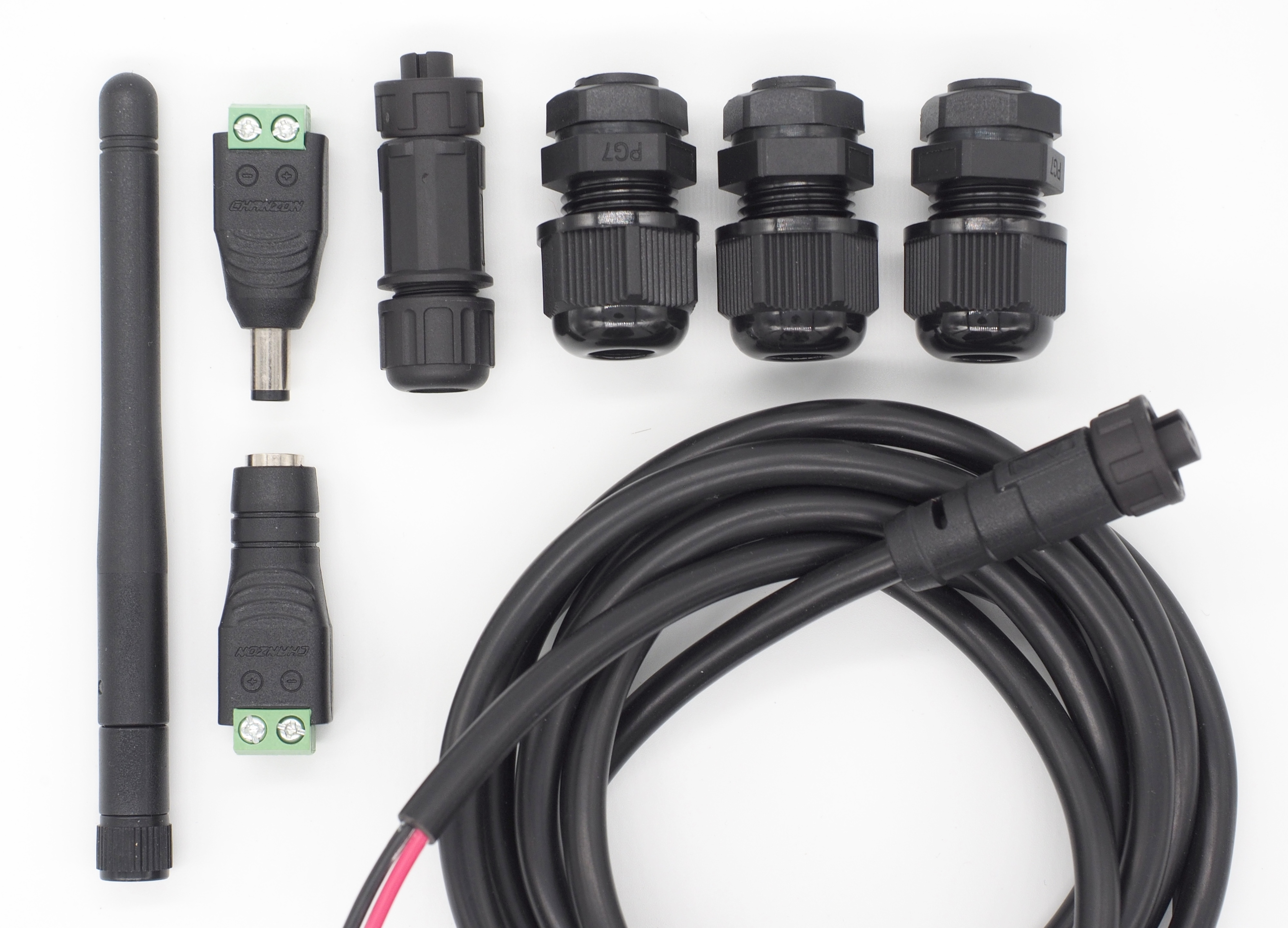
Additional accessories available separately:
- NMEA 2000 drop cable for bus-powered applications
- Various connector kits for custom installations
How to Use This Documentation
This documentation is structured to serve both end users seeking practical guidance and professional developers requiring detailed technical information.
For End Users
- Start with the Getting Started guide for setup and installation
- Explore Common Use Cases for application-specific guidance
- Reference Troubleshooting when issues arise
For Developers
- Review the Technical Reference for detailed specifications
- Study Software Development sections for custom applications
- Examine Design Files for integration planning
- Consult Advanced Configuration for performance optimization
Documentation Tips
- 💡 Quick Tips boxes provide shortcuts for common tasks
- ⚠️ Warning and Caution callouts highlight important safety information
- 🔧 Technical Details sections offer in-depth implementation information
- 📖 Cross-references link related topics throughout the documentation
Whether you're setting up your first marine computer or developing a custom industrial solution, this documentation will guide you through every step of the HALPI2 experience.
Getting Started
This guide will get your HALPI2 up and running in under 30 minutes and covers permanent installation. Follow these steps in order for the smoothest setup experience — start with a desktop setup to verify everything works, then proceed to permanent installation.
Safety and Handling Precautions
⚠️ Before You Begin
- Ensure power is disconnected from your electrical system before making connections
- Use appropriate fuses (3–5A) for power connections
- Handle the unit carefully - although rugged, dropping or impact can damage internal components
- Verify correct polarity when connecting power cables
- Avoid static electricity discharges - ground yourself and avoid rubbing cats and amber objects before touching internal components
What You'll Need
From your HALPI2 package:
- HALPI2 unit with pre-installed CM5 and NVMe SSD
- Power cable with E7T connector (2m length)
Optional items (included in the sales package):
- DC barrel connector pair (5.5 × 2.1 mm), when using a standard 12V "wall wart" type power supply
- Raspberry Pi WiFi/Bluetooth antenna (required if WiFi is used for initial setup)
Additional items (not included):
- 12V or 24V power source
- A separate computer for headless setup (if not using a connected display)
- Network cable (optional, for wired connection)
- Display with HDMI input (optional)
- USB keyboard and mouse (optional, for direct access)
💡 Quick Tip
Any network device such as a router or WiFi Access Point tends to use a 12V power supply that can be used to power the HALPI2. Check your pile of old hardware for one!
Desktop Setup
We recommend trying the HALPI2 on a desk or workbench before installing it permanently. The initial setup can be done either without a display (headless) over a network connection or with a connected display, keyboard, and mouse. A headless setup can be done either using a wired ethernet connection or the HALPI2's WiFi Access Point.
Step 1: Connect Essential Peripherals
For Initial Setup:
-
Network connection (required for headless installation):
- Connect Ethernet cable
- Connect the WiFi/Bluetooth antenna
-
Display connection (optional):
- Connect HDMI display for direct access
- USB keyboard and mouse if using display
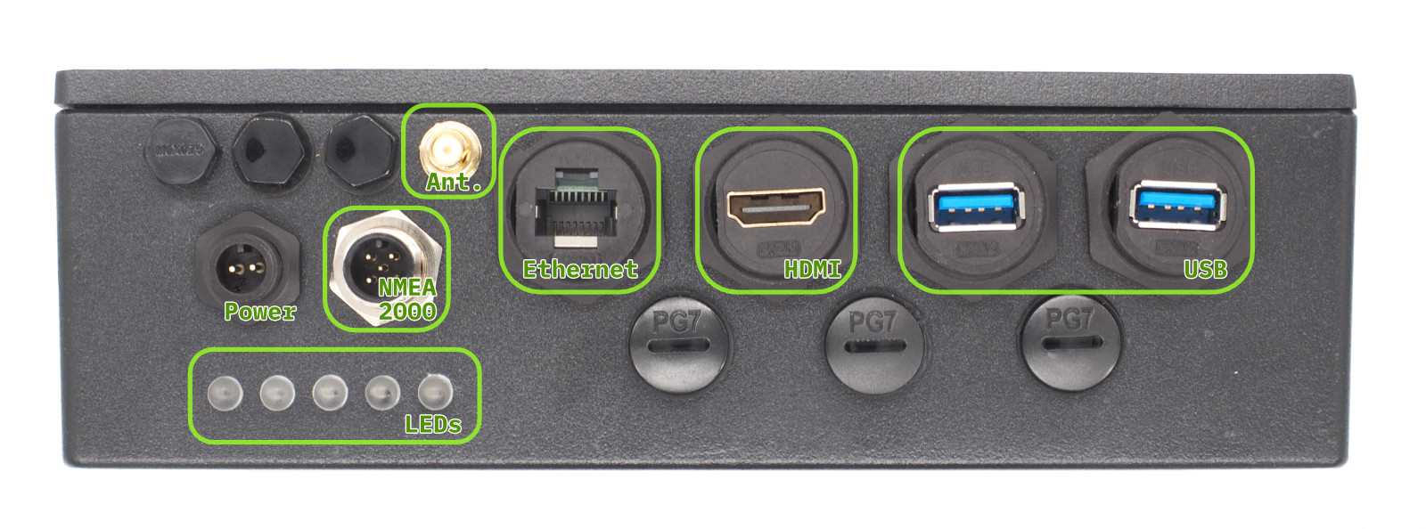 Front Panel Connectors
Step 2: NMEA 2000 Connection (Optional)
If you are installing the HALPI2 directly on a boat or have a desktop NMEA 2000 installation available, you can already connect it to the NMEA 2000 network.
An NMEA 2000 network consists of a backbone cable to which all devices connect using T-adapters and drop cables. Add a T-adapter to the NMEA 2000 network backbone. Connect the HALPI2's NMEA 2000 micro connector to the T-adapter using a NMEA 2000 drop cable.
Step 3: Power Connection
💡 Note on Powering with NMEA 2000
The HALPI2 can also be powered via the NMEA 2000 bus. See NMEA 2000 Bus Power Connection in the Permanent Installation section below.
For the desktop setup, we will use the provided E7T power cable. Connect the power cable wire ends to the female barrel plug as follows:
- Red wire = Positive (+)
- Black wire = Negative (-)
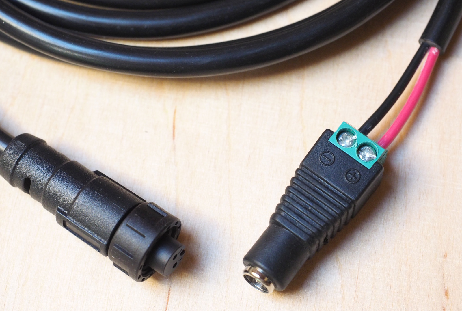 An example of the E7T to barrel connector wiring
Plug a standard 12V or 24V power supply into the barrel connector. Ensure the power supply is rated for at least 1A to handle the HALPI2's requirements.
⚠️ Warning
Due to the lack of a strain relief, the screw terminal barrel connector should only be used for temporary installations. Accidental pulling on the cable can disconnect and expose the wires.
First Boot
HALPI2 ships with a customized OpenPlotter image that includes necessary configurations and software for immediate use. If you prefer a different operating system, follow the instructions in the Software Guide.
Power on the HALPI2 by connecting the power supply if you haven't done so already. After a few seconds, the LED bar should start filling up with red lights, indicating that the super-capacitors are charging. The LEDs will turn yellow once the system is booting, and finally green when the operating system is running and the HALPI daemon is connected to the controller.
If you have a display connected, you should see the Raspberry Pi OS splash screen, and finally, a graphical desktop will appear.
💡 Tip
The status LED patterns are documented in the Operation Guide.
Accessing the HALPI2 without a Display
If you do not have a display connected, you can access the HALPI2 device via the WiFi Access Point or Ethernet connection. You need to download and install RealVNC's VNC Viewer to access the desktop remotely1.
Alternatively, you can use SSH to access the command line interface. The default username is pi and the password is raspberry. The nmtui tool can be used to configure NetworkManager settings in the terminal.
First, wait until the LEDs turn green, indicating that the system is fully booted. Then, follow these steps:
Option 1 - Connecting to HALPI2 via WiFi Access Point: The HALPI2 OpenPlotter image creates a WiFi Access Point named OpenPlotter with the password 12345678. Connect your computer to this network.
Option 2 - Connecting to HALPI2 via wired Ethernet: If you have connected the HALPI2 to your network via Ethernet, it will automatically obtain an IP address via DHCP.
You can connect to the device with VNC Viewer using the address openplotter.local or the assigned IP address. The username is pi and the password is raspberry.
First Boot Configuration
⚠️ Warning
The HALPI2 OpenPlotter image comes with default WiFi Access Point and user passwords. These must be changed during the first boot or anyone will be able to access your device.
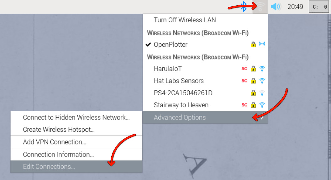
Changing the Access Point Password
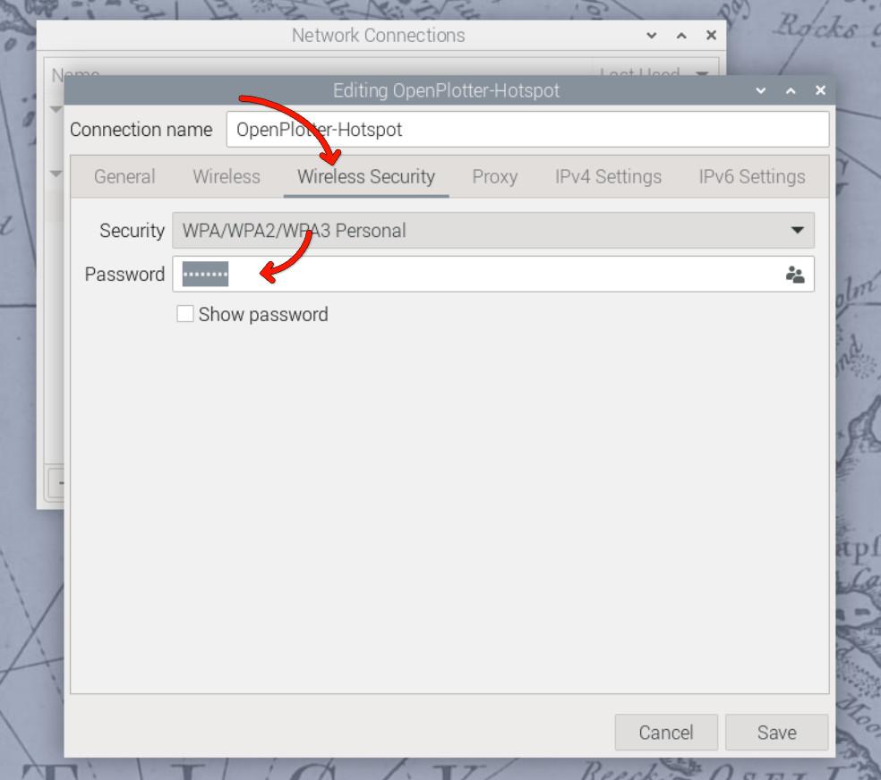
The WiFi access point password is changed in the network settings menu at the top right corner of the OpenPlotter desktop. Click on the network icon, then select Advanced Options and Edit Connections. Select the OpenPlotter-Hotspot connection and click the cogwheel icon to edit it. Change the password in the Wireless Security tab and save the changes.
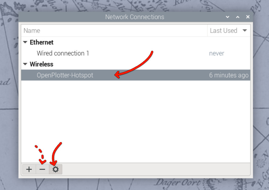
Alternatively, if you prefer to remove the access point altogether, you can remove it using the minus button in the Edit Connections dialog. However, if the final installation location uses a different WiFi network, the access point may be useful for initial configuration.
Changing the User Password
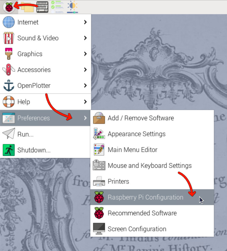
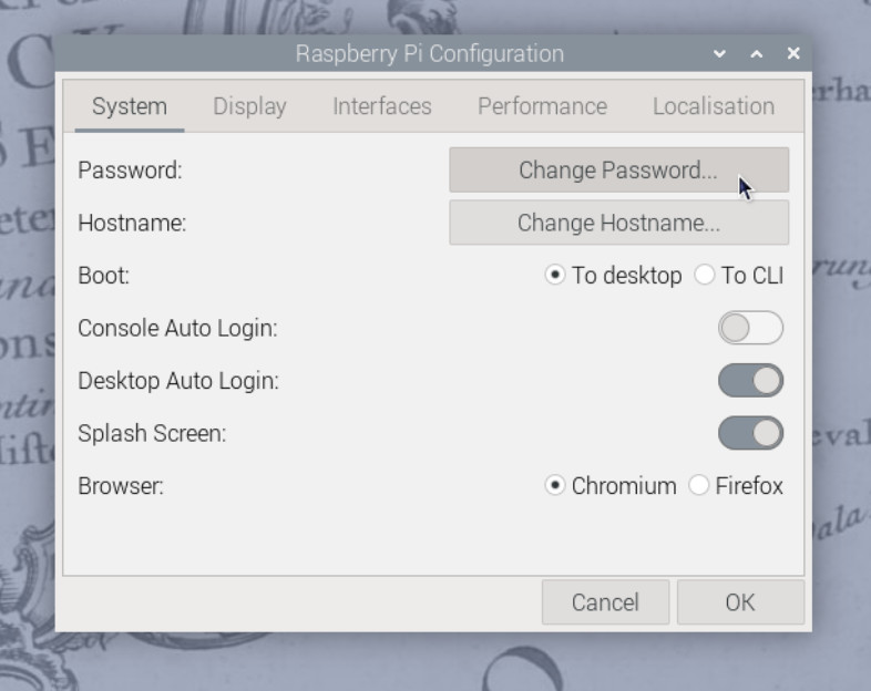
The default user password is raspberry. To change it, open the Raspberry Pi menu and navigate to Preferences > Raspberry Pi Configuration. In the System tab, click on Change Password and follow the prompts.
In the Raspberry Pi Configuration tool, you can also change the hostname (the name of the device on the network) and change localization settings such as time zone and keyboard layout.
You can also change the password using the terminal by running the command:
passwd
📖 Reference
Detailed OpenPlotter configuration steps are available in the OpenPlotter documentation.
Verifying NMEA 2000 Connection (Optional)
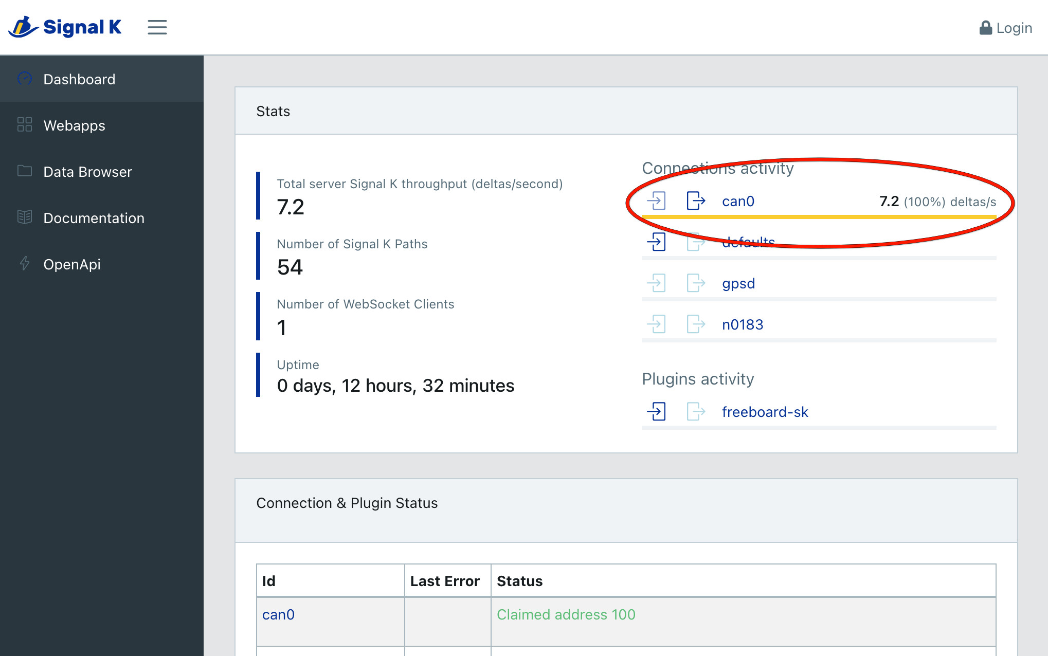
NMEA 2000 connectivity can be easiest verified by checking the Signal K server status. Open the web interface at http://openplotter.local:3000, either from the HALPI2 device itself or from another device on the same network. Observe the can0 connection activity: you should be seeing some traffic being received.
Shutting Down the Device
The HALPI2 is designed to shut down automatically when disconnected from the power supply. When you need to shut down the device, simply cut the power, either using an electrical panel switch or disconnecting the power connector. The system will automatically initiate a software shutdown sequence, ensuring that all applications close properly and the filesystem is safely unmounted.
If you choose to shut down the system using the desktop interface or command-line tools (such as the shutdown command), the device will automatically restart after approximately 5 seconds. This behavior is due to the power management system detecting that external power is still available.
During the shutdown process, you can monitor the system status through the LED indicators on the front panel. When power is initially cut, the green LEDs will dim to indicate a blackout condition. After 5 seconds, the LEDs will change to violet, providing a clear visual indication that the device is actively shutting down. Once the shutdown process is complete, all LEDs will turn off.
The shutdown process typically takes only a few seconds under normal conditions. However, in some cases, certain services may require additional time to stop properly. If this occurs, the device may deplete the super-capacitors almost completely before shutting down. This extended shutdown time is normal behavior and does not indicate a fault with the system.
Troubleshooting Quick Start Issues
Common and Uncommon Issues:
❌ No power/LEDs:
- Verify power connections and polarity
- Check fuse condition
- Ensure voltage is within 11-32V range
❌ WiFi Access Point not visible:
- Ensure antenna is properly connected
- Try to connect using a different device
- Check if the HALPI2 is fully booted (LEDs should be green)
- Try connecting via Ethernet first
❌ Cannot access the device using openplotter.local:
- There may be another device on the network with the same hostname
- Try using the assigned IP address instead (check your router's DHCP client list)
❌ Display connected but not showing anything:
- Ensure HDMI cable is securely connected
- Ensure the display is powered on and set to the correct input
- Try a different HDMI cable or port on the display
- Make sure the HALPI2 is on (LEDs should be yellow or green)
- If the LEDs are flashing in a rainbow pattern, the Compute Module 5 is not properly seated. This may be due to transportation damage. Follow the instructions in the User Guide to reseat the CM5 or contact support for assistance.
❌ Connected display is showing an error message about 'nvme':
- This indicates the NVMe SSD is not detected or not properly initialized. This can be due to transportation damage. Follow the instructions in the User Guide to reseat the NVMe SSD or contact support for assistance.
Getting Help:
- Documentation: Refer to specific sections for detailed troubleshooting
- Community: Join the Hat Labs community forums
- Support: Contact technical support for hardware issues
Permanent Installation
Once you've verified everything works on your desk, follow these steps for permanent mounting and wiring.
Planning Your Installation
💡 Quick Tip: Take photos of your existing wiring before making changes - it helps when troubleshooting later.
Take time to plan your installation. Consider:
- Mounting location - accessibility, protection, ventilation
- Cable routing - shortest runs, protection from damage
- Power source - dedicated circuit vs. shared, fusing requirements
- Network integration - NMEA 2000, Ethernet, WiFi coverage
- Environmental factors - temperature, moisture, vibration
Required Tools and Materials
Tools:
- Drill with bits
- Screwdriver set (PH2 Phillips, large flathead)
- Wire strippers and crimpers for power connections
- Multimeter for testing
- Heat gun or lighter (for heat-shrink tubing)
Materials (not included):
- Mounting screws (4mm or M4, depending on the mounting surface)
- Appropriate fuses (3-5A) or respectively rated electrical panel circuit breakers
- Marine-grade wire (1.5mm² or 16 AWG for power if the provided cable is too short)
- Heat-shrink tubing and terminals
- Cable ties and mounting clips
Mounting
Location Selection
Choose a mounting location that provides:
💡 Optimal Mounting Conditions
- Temperature range: -20°C to +60°C ambient
- Ventilation: Sufficient clearance around enclosure
- Protection: Away from direct water spray and mechanical damage
- Access: Easy access to connectors and status LEDs
- Support: Solid mounting surface capable of supporting 2kg + cables
- Space: Allow at least 100mm clearance in front of the panel connectors for cable management.
Even though this guide focuses on fixed installations, in practice it is often sufficient to place the device on a shelf or tabletop, provided it is stable and protected from moisture and impact.
Environmental Guidelines
Marine Installations:
- Mount above expected bilge water level
- Avoid areas with direct spray or standing water
- Consider boat movement and vibration, and secure all connections
- Use corrosion-resistant mounting hardware
Automotive Installations:
- Protect from engine heat and vibration
- Ensure adequate ventilation in enclosed spaces
- Consider accessibility for maintenance
- Use vibration-resistant mounting
Industrial Installations:
- Protect from process chemicals and extreme temperatures
- Consider electromagnetic interference sources
- Ensure compliance with local electrical codes
- Plan for routine maintenance access
Mounting Orientation
🔧 Recommended Orientation
Preferred: Connectors facing downward
- Reduces water ingress risk
- Improves cable management
- Easier access for maintenance
Acceptable: Connectors facing sideways
- Ensure adequate drainage
- Use cable entry seals
Avoid: Connectors facing upward
- Increases water ingress risk
- Makes cable management difficult
Mounting Steps
Step 0: Download and Print the Mounting Template
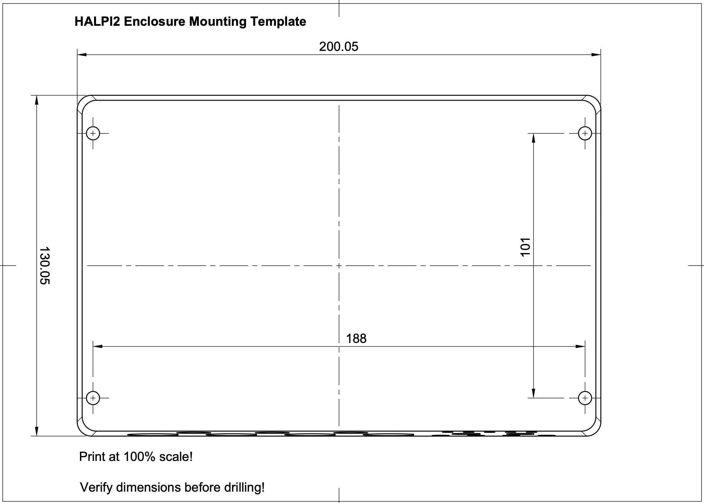
Download the HALPI2 Mounting Template and print it at 100% scale. This template will help you mark the mounting holes accurately. If you don't have access to a printer, you can also use the dimensions provided in the template to mark the holes manually, or use the enclosure itself to mark the holes directly on your mounting surface.
Step 1: Prepare the Mounting Surface
- Clean the mounting surface
- Mark mounting holes using the printed template
- Test fit the enclosure before installation
- Drill pilot holes for mounting screws
Step 2: Install the HALPI2
- Position the enclosure with connectors in preferred orientation
- Drive mounting screws - snug but do not over-torque
Permanent Power Installation
Power Source Selection
Option 1: Dedicated Power Connector
- Most reliable and flexible
- Supports full power capability
- Easier maintenance and troubleshooting
Option 2: NMEA 2000 Bus Power
- Simplifies wiring in marine installations
- Limited to 0.9A current draw
- Requires careful attention to voltage drop
Current Limiting Configuration
HALPI2 includes a built-in input current limiter that manages the initial super-capacitor charging and protects the installation from overcurrent conditions. The current limit can be set to either 0.9A or 2.5A, depending on your power source and application requirements. The default setting of 0.9A is suitable for most applications.
If you want to increase the initial start-up speed or need to power high-current peripherals, you can switch to the 2.5A setting. Follow the steps outlined in the User Guide to change the current limit setting.
Dedicated Power Connection
Cable Preparation
- Route the power cable from HALPI2 to power source
- Allow service loops at both ends
- Protect cable from chafing and damage
- Trim to length leaving adequate working room
Connection at Power Source
- Ensure wire protection by allocating a 3-5A circuit breaker or installing an inline fuse
- Strip wire ends to appropriate length
- Install terminals using proper crimping technique
- Connect to power source:
- Red wire: Positive (+) terminal
- Black wire: Negative (-) terminal
- Verify polarity with multimeter before energizing
Connection at HALPI2
The E7T connector is pre-wired and requires no field termination. Simply plug into the HALPI2 power socket.
NMEA 2000 Bus Power Connection
🔧 Prerequisites
- Current limit switch must be set to 0.9A
- NMEA 2000 network must have adequate power capacity
- Drop cable should be close to power feed to minimize voltage drop
Required Components
- NMEA 2000 drop cable (not included)
- T-connector for backbone integration (not included)
Installation Steps
- Power down all NMEA 2000 devices
- Open HALPI2 enclosure (see User Guide for instructions)
- Locate the carrier board power connector
- Unplug existing terminal block
- Connect the internal NMEA 2000 power terminal block to the carrier board power connector
- Verify current limit is set to 0.9A
- Connect to backbone using appropriate drop cable and T-connector
- Test installation before final closure
- Reassemble enclosure
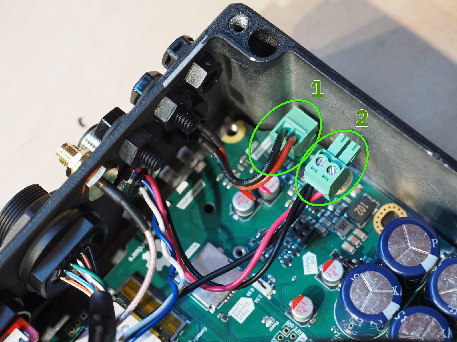 To power HALPI2 over NMEA 2000, unplug terminal block 1 and replace it with terminal block 2.
Network and Data Connections
NMEA 2000 Data Connection
Even when using a dedicated power connection, you may want NMEA 2000 data connectivity:
- Install T-connector on NMEA 2000 backbone
- Connect drop cable between T-connector and HALPI2
- Verify proper termination of NMEA 2000 network
- Test connectivity after installation
Ethernet Connection
For network connectivity:
- Use marine-grade or appropriate environment-rated cable
- Install cable glands or cable grommets if routing through bulkheads
- Provide service loops at both ends
- Test connectivity before final installation
WiFi/Bluetooth Antenna
- Install antenna on RP-SMA connector
- Position for optimal coverage - away from metal obstructions. In metal cabinets, a male to female RP-SMA extension cable may be required.
- Test signal strength in final position
Troubleshooting Installation Issues
Power Problems
❌ No power indication:
- Check fuse condition and rating
- Verify power source voltage (11-32V)
- Confirm correct polarity
- Test continuity of power cables
❌ Intermittent power:
- Check all connection tightness
- Inspect for corroded terminals
- Verify adequate wire gauge for current
Network Connectivity
❌ No NMEA 2000 communication:
- Verify network termination (120Ω at both ends)
- Check T-connector installation
- Confirm drop cable integrity
- Test with known-good device
❌ No Ethernet connectivity:
- Test cable with cable tester
- Verify switch/router configuration
- Check for IP address conflicts
- Confirm cable rating (Cat5e minimum)
Environmental Issues
❌ Moisture ingress:
- Inspect all seal conditions
- Verify connector orientation
- Check cable entry points
- Consider additional protection
❌ Overheating:
- Move away from heat sources
- Check for obstructed airflow around enclosure
Safety and Compliance
Electrical Safety
- Use appropriate fuses for overcurrent protection
- Ensure proper grounding per local codes
- Protect against short circuits with proper routing
Marine Installations
- Follow local or ABYC standards for electrical installations
- Use marine-grade components throughout
Industrial Installations
- Comply with local electrical codes
- Ensure proper EMI/RFI protection
- Document installation per facility requirements
Next Steps
Once your HALPI2 is running:
- Explore the User Guide for detailed operation instructions
- Review Common Use Cases for application-specific setup
- Check out the Technical Reference for advanced configuration options
- Join the community for tips, tricks, and support
System Operation
Status LED Indicators
HALPI2 features five RGB LEDs that provide visual feedback about system status and power conditions.
LED Status Quick Reference
| LED Pattern | Color | Meaning |
|---|---|---|
| Progressive fill | Red | Super-capacitor charging |
| Rainbow | Multi | System booting |
| All solid | Yellow | Solo mode operation |
| All solid | Green | Co-op mode operation |
| LED 1 flashing | Red | Input overvoltage warning |
| LED 5 flashing | Red | Super-capacitor overvoltage warning |
| All solid | Red | Watchdog timeout |
| Scrolling | Green/Yellow | Backup power active |
| All solid | Purple | Shutdown in progress |
| All solid | Blue | Shutdown to Standby in progress |
| All solid | Dim Red | Standby |
| All off | None | System off |
| All blinking rapidly | Red | Fault condition - contact manufacturer |
Super-Capacitor Voltage Indication
During operation, the LEDs function as a voltage indicator showing super-capacitor charge level:
- LED 1: 5.0-6.0V
- LED 2: 6.0-7.0V
- LED 3: 7.0-8.0V
- LED 4: 8.0-9.0V
- LED 5: 9.0-10.0V
Power Management and Shutdown Procedures
HALPI2 features a power supply designed to withstand voltage spikes, glitches and short-term outages.
Power System Overview
HALPI2's power management system consists of:
- Wide-range power supply (11-32 VDC input with protection up to 100 VDC)
- Super-capacitor backup system for graceful shutdowns during power loss
- Current limiting (0.9A or 2.5A selectable)
- Power loss detection and automatic shutdown initiation
- Input voltage and current monitoring
The system operates in two modes: Solo Mode and Co-op Mode.
Solo Mode Operation
Solo mode provides basic autonomous operation when the HALPI daemon is not running. The controller operates independently without software communication.
Solo Mode Characteristics
- No software communication required
- Basic power loss protection - monitors input voltage and responds to power loss
- Automatic shutdown via simulated power button presses
- Limited monitoring and configuration options
Solo Mode Power Loss and Shutdown
Power Loss Detection: The controller monitors input voltage and detects power loss. A blackout timer (default 5 seconds) prevents shutdowns during brief interruptions.
Automatic Shutdown Sequence:
- Controller detects power loss
- Blackout timer activates to distinguish glitches from actual power loss
- Simulated power button presses - controller sends double power-button presses to Compute Module
- Operating system responds and begins graceful shutdown
- Super-capacitors maintain power (typically 30-60 seconds available)
- 60-second timeout protection - forced power-off if graceful shutdown fails
- System remains off until power returns
- Automatic restart when power is restored
Manual Shutdown in Solo Mode:
- Normal operating system shutdown occurs
- System automatically restarts after 5 seconds if input power remains available
- For permanent shutdown, disconnect input power after initiating graceful shutdown
When Solo Mode is Active
Solo mode occurs:
- During initial boot before HALPI daemon starts
- If HALPI daemon fails to start or is disabled
- On unsupported operating systems without the daemon
- When the daemon has crashed or become unresponsive
💡 Solo Mode Reliability
Solo mode provides essential protection but is less reliable than Co-op mode. The controller relies on simulated button presses to request shutdown, which may not work if the system is frozen.
Co-op Mode Operation
Co-op mode provides full power management functionality when the HALPI daemon is running and communicating with the controller.
Co-op Mode Features
- Direct software communication - real-time data exchange between controller and daemon
- Watchdog timer protection - 30-second timeout ensures system stability
- Configurable shutdown behavior - customizable timing and commands
- Real-time monitoring - comprehensive power parameter monitoring
- Advanced configuration options
Co-op Mode Power Loss and Shutdown
Power Loss Detection: The controller monitors input power and communicates events directly to the HALPI daemon. The configurable blackout timer (default 5 seconds) allows brief power interruptions without initiating shutdown.
Automatic Shutdown Sequence:
- Controller detects power loss and communicates to HALPI daemon
- Blackout timer assessment - daemon evaluates if power loss exceeds threshold
- Shutdown command execution - daemon executes shutdown command (default:
/sbin/poweroff) - Operating system graceful shutdown - applications close and filesystems unmount safely
- Super-capacitor backup power provides energy throughout shutdown
- Controller monitors completion - tracks when Compute Module powers off
- 5V rail disabled when shutdown is complete
- System remains off until input power returns
- Restart management - based on configuration, system restarts automatically or remains off
Manual Shutdown in Co-op Mode:
- Standard graceful shutdown occurs when initiated through software
- System automatically restarts after 5 seconds if input power remains available
- To prevent automatic restart, disconnect power or configure
auto_restarttofalse
Watchdog Protection
Co-op mode includes watchdog timer protection:
- 30-second communication timeout - daemon must communicate with controller regularly
- Automatic recovery - system reboots if communication stops
- Software failure protection - ensures recovery from daemon crashes or system hangs
- "Feeding the watchdog" - daemon sends regular status updates to reset timer
When Co-op Mode is Active
Co-op mode occurs when:
- HALPI daemon is running and healthy
- Communication between daemon and controller is established
- System operates on a supported operating system
- Full system monitoring and control features are available
🔧 Verifying Co-op Mode
Check daemon status:
systemctl status halpidView controller state:
halpi statusFor further information on the
halpicommand, see the Software Guide.
Backup Power and Capacitor System
Both modes rely on the super-capacitor backup system for graceful shutdown protection:
Backup Power Duration:
- Super-capacitors provide 30-60 seconds of backup power
- Duration depends on system load and connected peripherals
- Sufficient time for safe file system closure and process termination
- Not designed for continued operation during extended outages
Charging Characteristics:
- Charging time: 25 seconds with 0.9A current limit
- Charging time: 9 seconds with 2.5A current limit
- Visual charging progress shown through LED progression (red fill pattern)
⚠️ Power Loss Protection Limitation
The super-capacitor system is designed for graceful shutdown, not continued operation. Do not rely on it for extended power outages.
Manual Shutdown Considerations
HALPI2 prioritizes automated operation and recovery, affecting manual shutdown behavior.
Automatic Restart Behavior
By default, HALPI2 restarts after manual shutdowns when input power remains available:
- Manual shutdowns result in normal operating system shutdown
- 5-second grace period follows shutdown completion
- System automatically restarts to maintain operational availability
- Ensures recovery from accidental shutdowns
Intentional Shutdown Methods
For permanent shutdown, use one of these approaches:
Power Disconnection Method:
- Initiate graceful shutdown through software
- Wait for shutdown completion (LEDs turn off)
- Disconnect input power to prevent automatic restart
Configuration Method:
- Disable automatic restart:
halpi config set auto_restart false - Initiate shutdown through software
- System remains off after shutdown completion
Standby Mode (Future):
🔧 Feature Status
Standby mode functionality is planned for future firmware releases. This will allow the Compute Module to be powered off while the HALPI2 controller remains active, waiting for wake-up events.
Hardware Guide
Enclosure Access
The HALPI2 features a powder-coated die-cast aluminium enclosure with pre-drilled holes for panel connectors. When internal modifications or maintenance are required, the enclosure can be accessed by following the procedures outlined below.
Opening the Enclosure
To access the internal components, begin by ensuring the unit is completely powered down and power cables are disconnected. The lid is secured with four countersunk M4x10 screws with PH2 heads. Use a PH2 screwdriver to remove these screws and remove the lid.
Reassembly
Before reassembling the enclosure, take time to verify that all internal connections are secure and properly seated. Route any cables carefully to avoid pinching or creating sharp bends.
It is easy to accidentally connect the flexible flat cables (FFCs) backwards. Observe the Contacts arrows on the silk screen to verify correct orientation.
Pay special attention to the lid gasket, checking for any damage, debris, or displacement that could compromise the enclosure's weather seal.
Reinstall the four M4x10 lid screws using the PH2 screwdriver. Do not over-tighten.
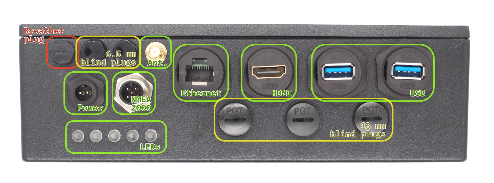
Panel Connectors
Standard Configuration
HALPI2 ships with a standard connector configuration suitable for most applications. The default layout includes:
- E7T power connector
- NMEA 2000 micro connector
- Gigabit Ethernet RJ45
- HDMI output
- 2× USB 3.0 Type-A
- 3× PG7 cable gland positions (with blind plugs)
- 2× RP-SMA antenna positions (with blind plugs)
- Breather plug for pressure equalization
 Front Panel Connectors and Blind Plugs. Connectors marked with green are included in the standard configuration. The yellow positions are blind plugs that can be replaced with connectors as needed. The red position is the breather plug that must not be removed.
Custom Connector Options
If you need different connector types, you can modify the panel configuration:
Removing Connectors
⚠️ Important
Only modify connectors when the unit is powered down and disconnected from all sources.
Plastic threads can be damaged by over-torquing. Use standard hex sockets but finger-tighten only.
-
Use appropriate socket size:
- Large connectors: 26mm socket
- M6 nylon bolts: 10mm socket
- RP-SMA connectors: 8mm socket
- PG7 positions: Large flathead screwdriver, 17mm socket
-
Remove carefully - plastic threads can be damaged by over-torquing
-
Keep removed parts for potential future use
Installing New Connectors
- Use only marine-grade or appropriate environment-rated connectors
- Ensure proper sealing - wide flange required on inside
- Finger-tighten only - do not over-torque plastic threads
- Test fit before final installation
Internal Layout
- The HALPI2 carrier board is the computer mainboard that houses the Compute Module 5 (CM5) on its bottom side and provides power management, indicators and connections for all interfaces.
Carrier Board Functional Areas
The major carrier board functional areas are illustrated in the image below.
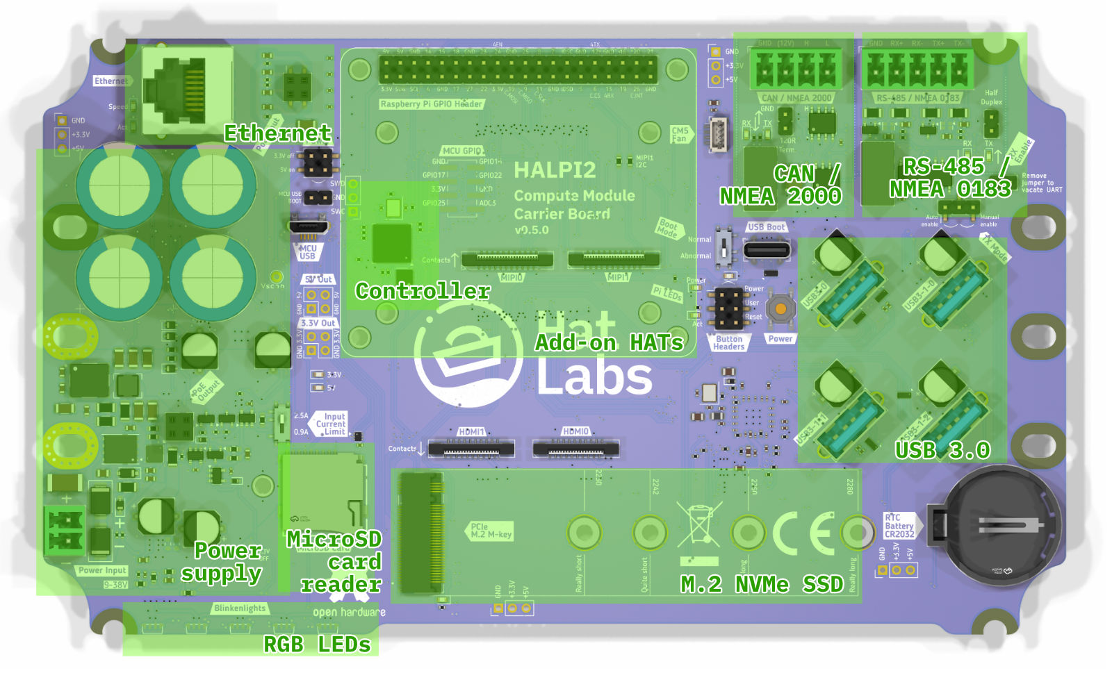 Carrier board top-side layout, showing key functional areas.
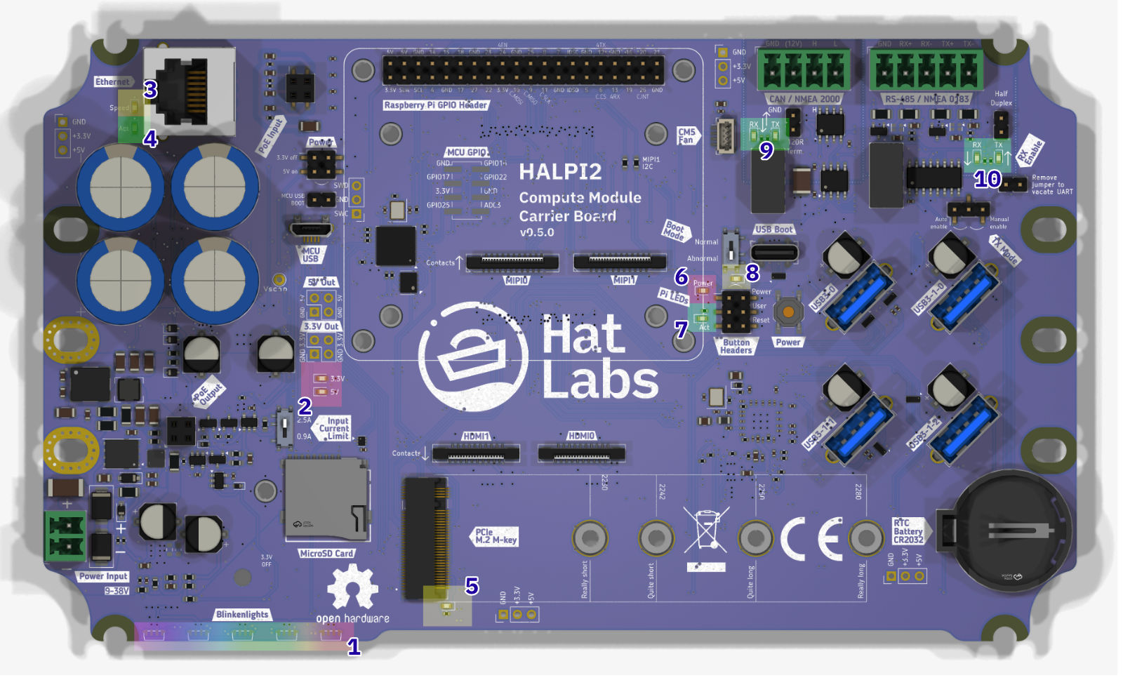
Carrier Board Connectors
The functionality is accessed through a number of on-board connectors, shown in the image below.
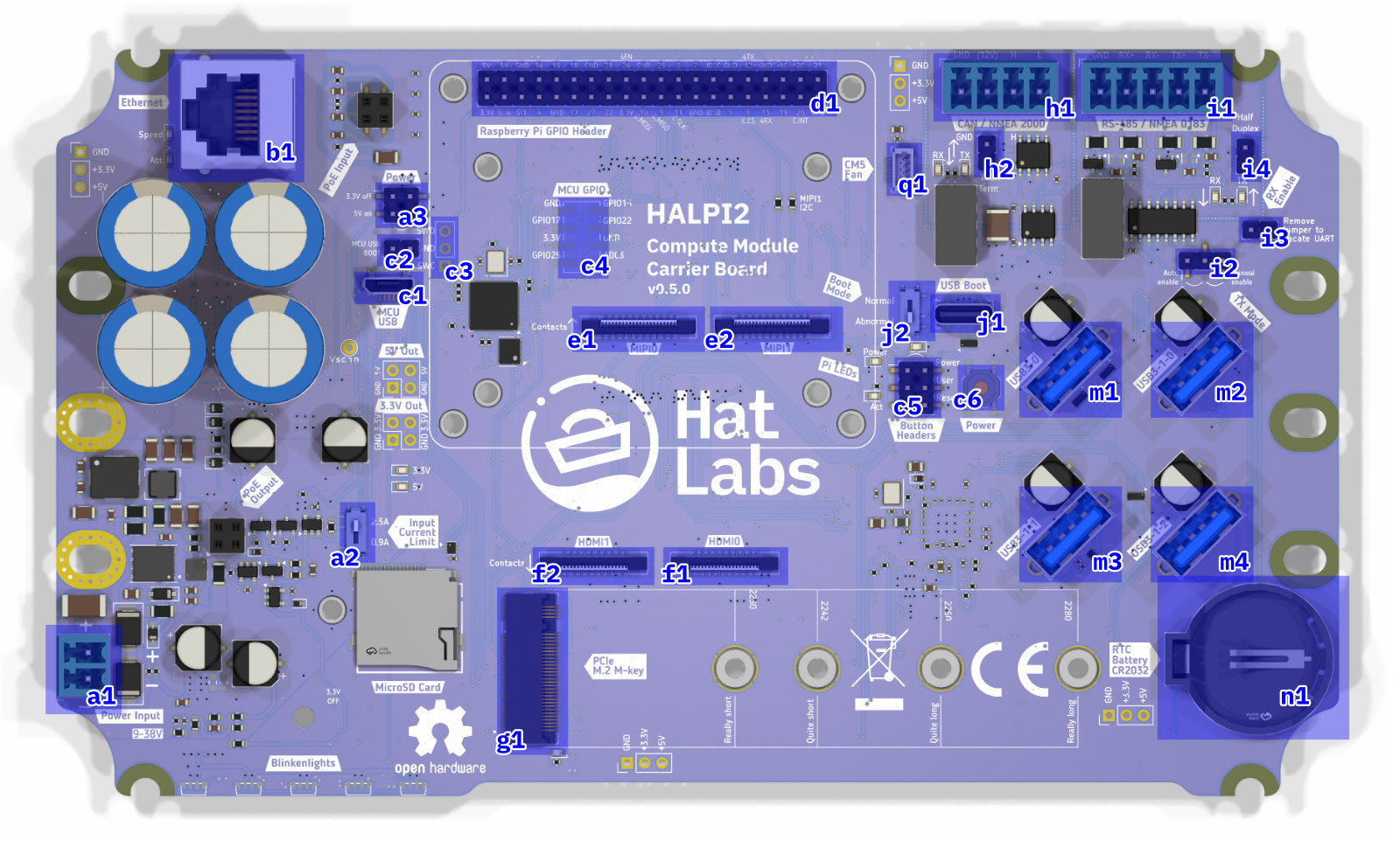 Carrier board connectors, top-side.
A list of the top-side connectors is given below.
| Label | Description |
|---|---|
| a1 | Power connector (Phoenix MC type, 3.81mm pitch) |
| a2 | Input current limit switch (0.9A or 2.5A) |
| a3 | Power control jumper. Short the 3.3V off pins to force the 3.3V rail off. Short the 5V on pins to force the 5V rail on. NB: On version 0.4.0 boards, the a3 and c2 connectors are organized differently. |
| b1 | Ethernet port (RJ45) |
| c1 | Controller USB port. Used for flashing the RP2040 microcontroller firmware. |
| c2 | MCU USB BOOT jumper header. Short the pins to put the RP2040 into USB boot mode. |
| c3 | Controller debugging header |
| c4 | Unpopulated controller GPIO header |
| c5 | Button headers. Used for connecting Power, Reset and User buttons. |
| c6 | Power button. Used for powering the Compute Module 5 on and off. |
| d1 | Raspberry Pi 40-pin GPIO header |
| e1 | MIPI0 connector for camera or display interface |
| e2 | MIPI1 connector for camera or display interface |
| f1 | HDMI0 connector |
| f2 | HDMI1 connector |
| g1 | M.2 NVMe SSD connector |
| h1 | CAN FD interface (Phoenix MC type, 3.81mm pitch) |
| h2 | CAN terminator jumper. Short the pins to enable the CAN FD bus terminator. |
| i1 | RS-485 interface (Phoenix MC type, 3.81mm pitch) |
| i2 | RS-485 auto/manual enable jumper. |
| i4 | XRS-485 RX Enable jumper. Short the pins to enable RS-485 traffic receiving. |
| j1 | Compute Module USB Boot connector. Used for flashing the Compute Module 5 firmware. |
| j2 | Compute Module Boot Mode selection switch. Set to "Normal" for normal operation and "Abnormal" for USB boot mode. A warning LED will light up when the switch is set to "Abnormal". |
| m1 | USB3 connector 0. Connected directly to the CM5. |
| m2 | USB3 connector 1-0. Connected to the onboard USB3 hub. |
| m3 | USB3 connector 1-1. Connected to the onboard USB3 hub. |
| m4 | USB3 connector 1-2. Connected to the onboard USB3 hub. |
| n1 | CR2032 battery holder for RTC (Real Time Clock) |
| q1 | CM5 fan connector. The fan can be used for improving air circulation inside the enclosure. It is not needed when the standard enclosure is used. |
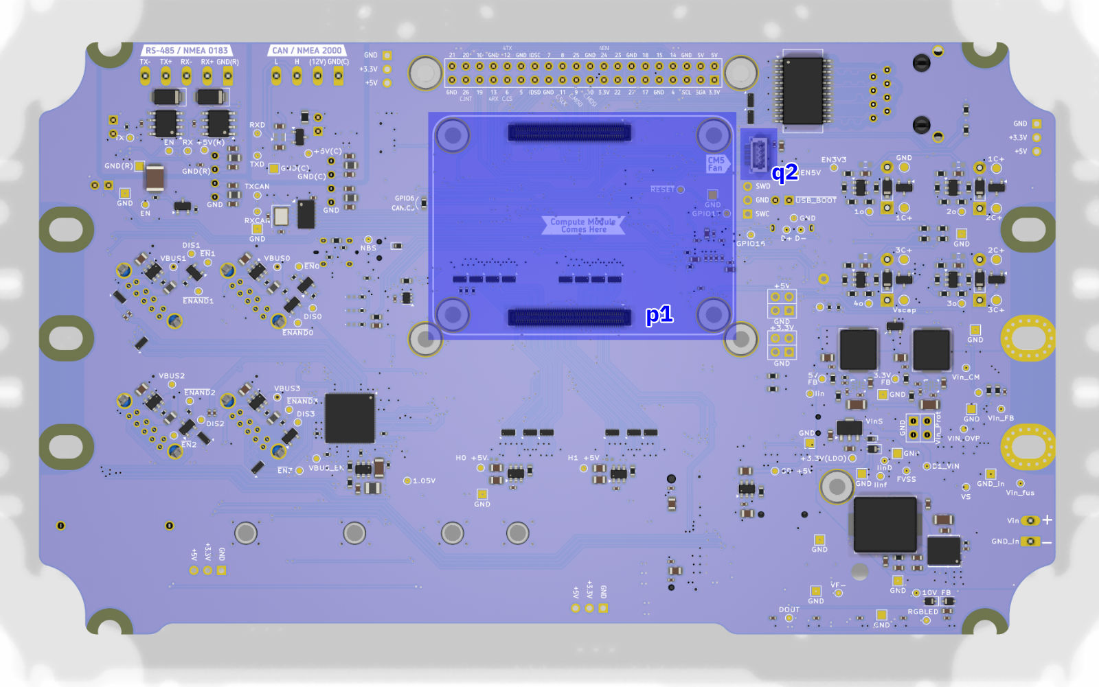 Carrier board connectors, bottom-side.
A list of the bottom-side connectors is given below.
| Label | Description |
|---|---|
| p1 | Compute Module 5 connector. |
| q1 | CM5 fan connector, alternative location. This header can be used to connect a CPU fan over the CM5 module when using a custom enclosure. NB: Connectors q1 and q2 are connected in parallel and must not be used simultaneously. |
Finally, the WiFi and Bluetooth antenna connector resides on the Compute Module 5 itself. It is shown in the image below.
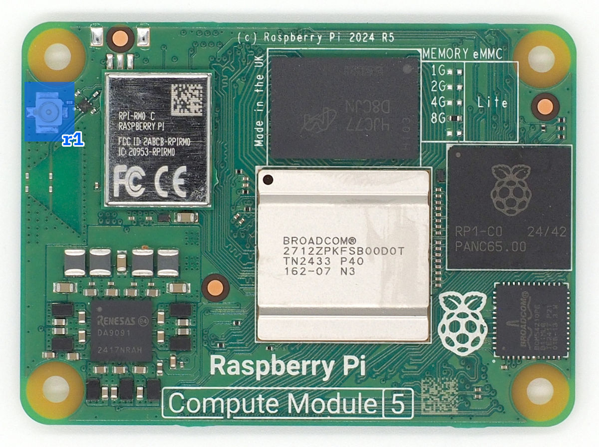 U.FL antenna connector on the Compute Module 5.
| Label | Description |
|---|---|
| r1 | U.FL connector for the WiFi and Bluetooth antenna. |
Blinkenlights
The carrier board features several status LEDs for system monitoring.
 Carrier board status LEDs and their colors.
The status LEDs provide information about the system's power and activity states. A list of the status LEDs is given below.
| Label | Color | Description |
|---|---|---|
| 1 | RGB | Five RGB LEDs. These LEDs are used for indicating system status and activity on the front panel. |
| 2 | Red | Power LEDs for the 3.3V and 5V rails. These LEDs indicate the power status of the respective voltage rails. |
| 3 | Yellow | Ethernet speed indicator. On when the Ethernet port has negotiated a 100/1000 Mbps connection. |
| 4 | Green | Ethernet activity indicator. Flashes when there is network traffic on the Ethernet port. |
| 5 | Blue | SSD activity indicator. Flashes when there is read/write activity on the M.2 NVMe SSD. |
| 6 | Red | Pi Power status indicator. Lit when the system is powered but shut down. |
| 7 | Green | Pi activity indicator. Flashes when there is activity on the Raspberry Pi. |
| 8 | Amber | Abnormal Boot Mode warning. On when the USB boot mode switch is set to "Abnormal". This indicates that the device is set to flash via the USB Boot connector and won't boot normally. |
| 9 | Green | CAN TX/RX LEDs. These LEDs flash when data is either received (RX) or transmitted (TX) on the CAN interface. |
| 10 | Green | RS-485 TX/RX LEDs. These LEDs flash when data is either received (RX) or transmitted (TX) on the RS-485 interface. |
The RGB LED patterns are documented in the Operation Guide.
Current Limiting Configuration
The carrier board features a current limiting switch to configure the maximum current supplied to the peripherals. To locate the switch, refer to the location of switch a2 in the image in the Carrier Board Connectors section.
🔧 Current Limit Settings
0.9A Setting (Default):
- Mandatory for NMEA 2000 bus power
- Suitable for basic operation
2.5A Setting:
- For high-power peripherals
- Faster super-capacitor charging
- Only with dedicated power connection
To change the current limit setting, first power down the HALPI2 completely and remove the enclosure lid following the procedure outlined in the Enclosure Access section. Locate the current limit switch on the carrier board and move the switch to the desired position (either 0.9A or 2.5A). Once the setting has been changed, reassemble the enclosure ensuring all connections remain secure.
Using HATs
HAT Compatibility
HALPI2 supports standard Raspberry Pi HATs through its 40-pin GPIO header, maintaining full electrical and mechanical compatibility with the Raspberry Pi HAT specification. The carrier board provides the same GPIO pinout as a standard Raspberry Pi, allowing most HATs designed for Raspberry Pi 4 and 5 to work without modification. This compatibility extends to both official Raspberry Pi HATs and third-party expansion boards that follow the HAT standard.
Physical Constraints
The HALPI2 enclosure provides 45mm of vertical clearance above the carrier board, sufficient to accommodate up to two stacked HATs. The area to the left of the outlined HAT installation area is occupied by the super-capacitors, limiting the available space for HATs that extend beyond the standard 65mm × 56mm footprint. Pay special attention to HATs with side-mounted connectors. Connectors facing "south" or "east" should be fine but those facing "west" may interfere with the super-capacitors.
GPIO Pin Conflicts
Several GPIO pins are utilized by HALPI2's built-in interfaces and must be considered when selecting compatible HATs. The following table details the reserved GPIO pins and their functions:
| GPIO Number | Function | Interface | Notes |
|---|---|---|---|
| GPIO 2 | I2C SDA | System I2C | Can be shared; address 0x6d reserved |
| GPIO 3 | I2C SCL | System I2C | Can be shared; address 0x6d reserved |
| GPIO 6 | SPI CS | CAN FD | Custom chip select for CAN controller |
| GPIO 9 | SPI MISO | CAN FD | Shared SPI0 bus |
| GPIO 10 | SPI MOSI | CAN FD | Shared SPI0 bus |
| GPIO 11 | SPI SCK | CAN FD | Shared SPI0 bus |
| GPIO 12 | UART TX | RS-485 | UART4 transmit |
| GPIO 13 | UART RX | RS-485 | UART4 receive |
| GPIO 24 | RS-485 EN | RS-485 | Enable signal (manual mode only) |
| GPIO 26 | CAN INT | CAN FD | Interrupt line for CAN controller |
Interface Sharing and Conflicts
The I2C bus on GPIO 2 and 3 can be shared with HAT devices, as I2C supports multiple devices on the same bus. However, HATs must not use I2C address 0x6d, which is reserved for the HALPI2 system controller. Most I2C HATs will work without issue, but verify the I2C addresses used before installation.
The SPI0 bus used for the CAN FD interface can potentially be shared with other SPI devices, as HALPI2 uses custom chip select (GPIO 6) and interrupt (GPIO 26) pins. HATs using SPI0 with the standard chip select pins (GPIO 7 or GPIO 8) may coexist with the CAN interface but may require additional device tree overlay configuration.
Disabling Built-in Interfaces
If a HAT requires exclusive use of pins occupied by HALPI2's built-in interfaces, these interfaces can be disabled through hardware modifications. The CAN FD interface can be completely freed by removing the GPIO6-CAN.CS solder jumper located on the bottom side of the carrier board. This modification disconnects the CAN controller from the SPI bus, freeing GPIO 6, 9, 10, 11, and 26 for HAT use.
The RS-485 interface can be disabled by removing the RX Enable jumper (i4) on the carrier board. This prevents the RS-485 transceiver from receiving data and frees GPIO 12 and 13 for other uses. If manual transmit enable control is not required, GPIO 24 can also be repurposed by setting the RS-485 auto/manual enable jumper (i2) to automatic mode.
Installation Procedure
Begin installation by powering down the system and disconnecting all power sources. Remove the enclosure lid following the procedure outlined in the Enclosure Access section.
Version 0.5.0 and later carrier boards include pre-installed M2.5 threaded inserts at the four HAT mounting positions, simplifying installation. Earlier v0.4.0 boards require M2.5 nuts to be installed manually. For nut installation, the carrier board must be temporarily dismounted. It is possible to do this without disconnecting all cables.
For many common HATs, 15mm standoffs are suitable, but measure the HAT's female header height to ensure correct clearance. The male header base is 2.5mm high, so add this to the female header height to determine the required standoff length.
Thread the standoffs into the mounting holes or secure them with nuts from below on v0.4.0 boards. Align the HAT with the 40-pin GPIO header, ensuring all pins are properly positioned before applying even pressure to seat the connector. The HAT should sit parallel to the carrier board with no visible gap at the GPIO connection.
Secure the HAT using M2.5 screws or additional standoffs through the HAT's mounting holes into the standoffs. These screws are not included with HALPI2 and must be sourced separately. Tighten the screws just enough to secure the HAT without flexing the circuit board.
Cable Management
If the HAT includes external connectors that need to be accessed from outside the enclosure, consider installing appropriate panel connectors in the available PG7 cable gland positions. This maintains the enclosure's environmental protection while providing convenient external access.
Removal Procedure
HAT removal follows the installation procedure in reverse. Power down the system completely and disconnect all power sources before opening the enclosure. Remove the M2.5 mounting screws and carefully lift the HAT straight up from the GPIO header, avoiding any lateral force that could bend the header pins.
If the HAT seems stuck, check for any overlooked mounting hardware or cables before applying additional force. Some HATs with tight-fitting connectors may require gentle rocking motion while pulling upward. Rock the HAT in the north-south direction; rocking east-west risks bending the header pins when the connector suddenly releases.
Software Configuration
After hardware installation, the HAT may require software configuration to function properly. Many HATs include device tree overlays that must be enabled in the Raspberry Pi configuration. Edit /boot/firmware/config.txt to add the appropriate dtoverlay lines as specified in your HAT's documentation.
📖 Related Information
- GPIO pinout reference: See Hardware Reference
- Software configuration: See Advanced Configuration
- Enclosure modifications: See Custom Connector Options
Replacing the NVMe SSD
SSD Compatibility
HALPI2 supports M.2 2230-2280 NVMe SSDs in the standard single-sided configuration. While shorter 2230 drives can be double-sided due to the additional clearance at that mounting position, longer drives must be single-sided to fit on the carrier board.
Compatibility can only be guaranteed with SSDs supplied by Hat Labs and official Raspberry Pi SSDs. If considering a third-party drive, verify its compatibility with Raspberry Pi 5 before purchase by checking user reports and compatibility lists online. Common issues with incompatible drives include excessive power consumption, overheating, and boot failures or system instability.
Preparing the New SSD
Before installing a new SSD in HALPI2, the operating system should be flashed onto the drive. While it is possible to flash the SSD after installation using the CM5's USB Boot connector (j1), using an external USB to NVMe adapter is easier and faster. The flashing procedure is described in the Software Guide.
Disabling System 3.3V Voltage
The super-capacitors can keep the carrier board 3.3V rail powered for a significant amount of time after the main power is disconnected. Since the SSD is powered from the 3.3V rail, the rail must be disabled to ensure the SSD is completely unpowered before removal or installation.
Begin by powering down HALPI2 and disconnecting the power supply. Open the enclosure following the procedure described in the Enclosure Access section.
Locate the "3.3V off" jumper on the carrier board. Its location varies depending on the board version. On the v0.4.0 boards, the jumper is very close to the super-capacitors, on their "south" side. On v0.5.0 and later boards, locate the "Pow.Ctrl" header to the "east" of the super-capacitors. The "3.3V off" pins are the top two ones on the header.
Move the jumper to short the 3.3V off pins. This will disable the 3.3V rail, indicated by the LEDs turning off.
Removal Procedure
The M.2 slot is located at the south edge on the carrier board. Refer to the image in the Carrier Board Connectors section to locate the M.2 connector labeled g1.
Using a PH1 screwdriver, remove the M2.5 mounting screw. Once the screw is removed, the SSD will spring up at an angle. Gently lift the drive from the mounting end and wiggle it out of the M.2 connector. Handle the SSD by its edges to avoid damaging the components or connectors.
Installation Procedure
Insert the prepared SSD into the M.2 connector at approximately a 30-degree angle, ensuring the notch in the SSD aligns with the key in the connector. The drive should slide in smoothly without requiring force. Once fully seated, press down the mounting end of the SSD until it lies flat against the standoff.
Secure the SSD with the M2.5 mounting screw using a PH1 screwdriver. Tighten the screw just enough to hold the drive firmly in place. The SSD should lie perfectly flat with no visible bend or flex.
Once the SSD is in place, remove the jumper from the 3.3V off pins to re-enable the 3.3V rail. Keep the jumper stored on the header for future use.
Reassemble the enclosure as described in the Enclosure Access section. For any software configuration or troubleshooting, refer to the Software Guide.
📖 Related Information
- System images: See Software Guide
- Boot procedures: See System Operation
- Hardware access: See Enclosure Access
Replacing the Compute Module 5
Prerequisites
Replacing the Compute Module 5 requires careful handling due to the delicate nature of the board-to-board connectors. The CM5 uses two high-density connectors that can be easily damaged if excessive force or improper technique is used. Only unmount an existing module if it is absolutely necessary, such as when the module is damaged or needs to be upgraded. Damage to the compute module mounting connectors on either the CM5 or the carrier board is not covered by warranty.
Before beginning, ensure you have thermal pads available for heat transfer. The standard configuration uses a 1mm thick pad on the SoC and 2mm thick pads on the RP1 chip and internal power supply components. Existing thermal pads can be reused if they remain intact and clean.
Accessing the Compute Module
Power down the HALPI2 and disconnect the power source. Remove the enclosure lid following the procedure in the Enclosure Access section. To access the CM5, which is mounted on the underside of the carrier board, you must first unmount the carrier board from the enclosure. To keep track of the numerous cables connected to the carrier board, it is recommended to take a few photos of the connections before proceeding.
Disconnect any cables that prevent the carrier board from being lifted. Remove the carrier board mounting screws and lift the board from the enclosure.
Removing the Existing Module
‼️ Caution
If the CM5 module is disconnected one connector at a time, the twist forces can rip the connector off the CM5 module. This damage is not covered by warranty.
The CM5 is secured by two board-to-board connectors that require careful handling. Never use metal tools for this procedure as they can damage the connectors or nearby surface-mounted components. Use a wooden or plastic spudger, guitar pick, or similar non-conductive tool.
Position your tool at the center of left-hand side short edge of the CM5 module, between the module and the carrier board. Press down firmly at the right-hand side corners. Gently pry upward with minimal force – the module should be released with a light click, with both connectors detaching simultaneously.
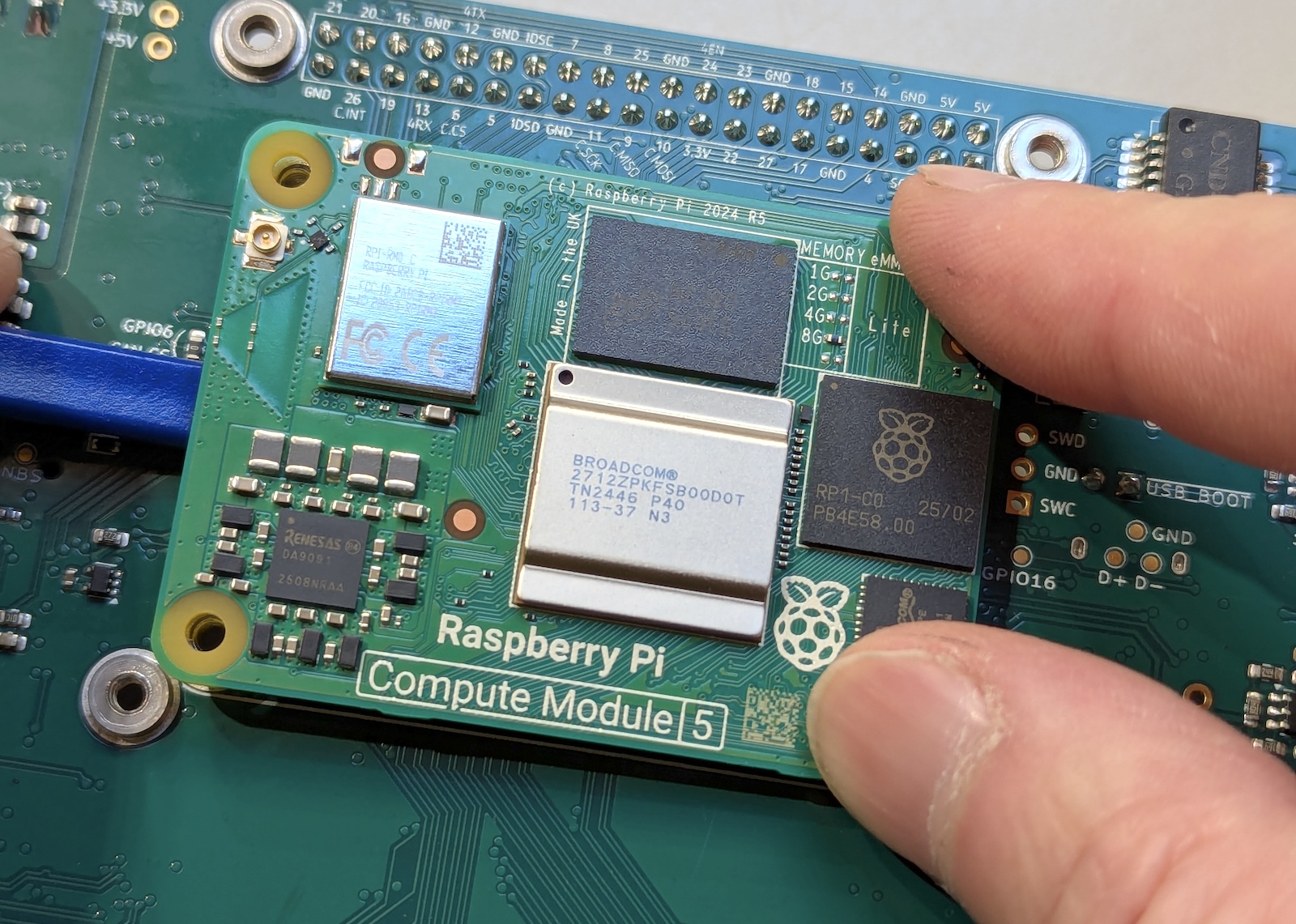 Unmount the CM5 module by pressing down at the right edge corners while prying upward at the center of the left edge. Both connectors should detach simultaneously.
Installing the New Module
Align the new CM5 module with the carrier board connectors, using the silk screen outline on the carrier board as a guide. The module outline printed on the carrier board should match the CM5's physical dimensions exactly when properly oriented.
Once aligned, apply gentle, even pressure at the connector locations on both short edges of the module. You should feel the connectors engage with a subtle click. Press firmly but avoid flexing the carrier board – support the board from underneath if necessary. Both connectors must be fully seated for proper operation.
Now, add thermal pads on the CM5 module. The thermal pads should be positioned correctly: 1 mm pad on the main SoC, and 3 mm pads on the RP1 chip and power supply components. If reusing existing pads, ensure they are clean and properly positioned.
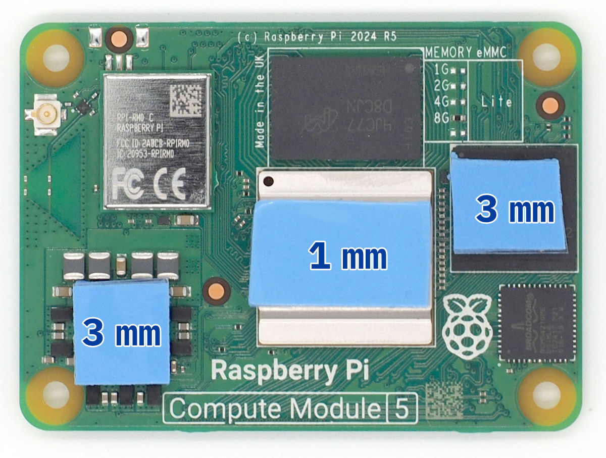 Thermal pad placement on the Compute Module 5. Use 1 mm thick pad on the SoC (center) and 3 mm thick pads on the RP1 and power supply components. The actual thermal pad shapes and sizes may vary.
Antenna Connection
Before remounting the carrier board, connect the U.FL antenna cable to the CM5's wireless antenna connector. This connection is impossible to access once the carrier board is reinstalled. The U.FL connector requires careful alignment and firm pressure to seat properly. You should feel a distinct snap when the connector is fully engaged. Be careful not to bend the connector shell during installation.
Final Assembly
Inspect the module installation to ensure both connectors are fully seated and the module lies flat against the carrier board with no gaps. The thermal pads should make contact with the module's heat-generating components.
Position the carrier board back in the enclosure, ensuring the thermal pads on the CM5 align with the corresponding heat spreading areas on the enclosure bottom. Reinstall all carrier board mounting screws and reconnect any cables that were disconnected during removal.
Complete the reassembly following the standard enclosure closure procedure. On first boot, the system should recognize the new CM5 automatically.
⚠️ Connector Warning
The board-to-board connectors are the most fragile components in this procedure. Never use metal tools near the connectors, apply only vertical force when removing or installing, and ensure perfect alignment before applying pressure. Damaged connectors typically require carrier board replacement.
📖 Related Information
- System setup after replacement: See Software Guide
- Boot troubleshooting: See Troubleshooting
- Thermal management: See Hardware Reference
Interfaces and Connectivity
CAN FD / NMEA 2000
HALPI2 features a fully isolated CAN FD interface that supports both marine NMEA 2000 networks and automotive or industrial applications. The interface provides high-speed data communication with complete electrical isolation for noise immunity.
Interface Specifications
The CAN FD interface supports both standard CAN and CAN FD protocols. For NMEA 2000 applications, the interface operates in regular CAN mode at the standard 250 kbps data rate. When used for automotive or industrial applications, the interface can utilize the full CAN FD capabilities with data rates up to 8 Mbps.
The front panel features a Micro-C connector that is compatible with standard NMEA 2000 cabling and components. This allows direct integration with existing marine networks using standard T-connectors and drop cables.
Power Configuration and Network Loading
HALPI2's impact on NMEA 2000 network power depends on the power configuration chosen. In the standard configuration using external power via the E7T connector, the device requires no power from the NMEA 2000 network, resulting in a Load Equivalency Number (LEN) of 0.
When configured for NMEA 2000 bus power, the device's current draw needs to be limited to 0.9A by the internal current limiter. This corresponds to a LEN rating of 18. When powering HALPI2 via NMEA 2000, the device should be connected to the network backbone close to the power feed cable to minimize voltage drop and ensure reliable operation.
Hardware Configuration
The carrier board includes a 120Ω termination resistor that can be enabled via a jumper. Device termination should be avoided in NMEA 2000 applications as the standard does not allow it. However, for automotive or industrial applications where point-to-point communication is used, the jumper can be set to enable the termination resistor.
For network diagnostics and troubleshooting, the carrier board features dedicated RX and TX LEDs that indicate network activity. These LEDs provide immediate visual feedback about data transmission and reception, making it easier to diagnose connectivity issues.
Network Installation
Connection to NMEA 2000 networks is accomplished using a standard T-connector (not supplied) installed on the network backbone and a drop cable connecting the T-connector to HALPI2's Micro-C connector.
Software Integration
The CAN interface integrates seamlessly with Linux through the SocketCAN framework, appearing as network device can0. This standard interface allows the use of common Linux CAN utilities for monitoring and diagnostics. The network interface is preconfigured in the operating system images provided by Hat Labs.
Signal K server integration is preconfigured in the OpenPlotter image, automatically detecting and utilizing the CAN interface for NMEA 2000 data processing. The Signal K server handles PGN decoding and provides web-based access to real-time network data.
Troubleshooting
Network troubleshooting begins with the RX/TX LEDs on the carrier board. Normal operation shows intermittent LED activity corresponding to network traffic. Missing RX activity may indicate wiring issues or improper termination, while missing TX activity could suggest network conflicts or wiring.
The Linux candump command can be used to monitor the CAN bus directly from the command line. This tool provides detailed information about all messages on the bus, allowing for in-depth diagnostics. In its simplest form, you can run:
candump can0
This will display all incoming raw CAN messages in real-time.
The Signal K server dashboard provides additional network monitoring capabilities. It displays real-time NMEA 2000 data rates from the CAN interface. The data browser tool allows viewing of decoded NMEA 2000 data.
📖 Related Information
- Power configuration: See Getting Started
- Software setup: See Software Guide
- Network troubleshooting: See Troubleshooting Guide
RS-485 (NMEA 0183)
HALPI2 includes an isolated RS-485 interface that provides serial communication for marine NMEA 01831 networks and industrial applications.
Technically, NMEA 0183 uses the RS-422 standard, but RS-485 is downwards compatible, allowing HALPI2 to communicate with both RS-422 and RS-485 devices.
Interface Specifications
The RS-485 transceiver operates at speeds up to 10 Mbps, though typical NMEA 0183 applications use standard baud rates of 4800 or 38400 bps. The interface features galvanic isolation and is compliant with the NMEA 0183 specification, protecting the HALPI2 from ground loops and electrical noise commonly found in marine environments.
The interface is connected internally to UART 4 of the Raspberry Pi, appearing as /dev/ttyAMA4 in the Linux operating system. This standard serial device can be accessed by any application that supports serial communication, including Signal K server, OpenCPN, and custom software applications.
Hardware Configuration
The carrier board includes dedicated RX and TX LEDs that indicate communication activity on the RS-485 interface. These LEDs provide immediate visual feedback during installation and troubleshooting, making it easy to verify that data is being transmitted and received correctly.
When operating as a generic RS-485 interface, the device can be configured for either automatic or manual transmit enable mode. In the manual mode, a GPIO pin is used to control the transmit enable signal, allowing software to manage when the interface is in transmit or receive mode. This is required for multi-talker applications in which the interface needs to be in a recessive state when not transmitting. The automatic mode allows the hardware to activate the transmit enable signal when data is sent, simplifying the setup for single-talker applications.
Furthermore, the RS-485 interface supports a half-duplex mode, allowing it to operate in both transmit and receive modes on the same pair of wires.
The interface can also be completely disabled via hardware configuration if UART 4 is needed for other purposes.
Wiring and Connectivity
The RS-485 interface requires a cable gland or panel connector that must be supplied by the user. One good option is an SP13 pigtail panel connector. The interface is downward compatible with RS-422 signaling used in NMEA 0183, supporting both RS-485 multi-talker networks and RS-422 single-talker-multiple-listener networks. It uses balanced differential pairs, labeled TX+/TX- and RX+/RX-.
Software Integration
The OpenPlotter image comes preconfigured with the RS-485 interface ready for NMEA 0183 applications. The Signal K server automatically detects the interface and will automatically receive transmitted NMEA 0183 data.
For custom applications, the interface behaves as a standard Linux serial port. Applications can open /dev/ttyAMA4 and configure the baud rate, data bits, stop bits, and parity as required by the connected equipment. Python, Node.js, and C/C++ applications can all easily access the interface using standard serial communication libraries.
Common Applications
In marine environments, the RS-485 interface typically connects to GPS receivers, depth sounders, wind instruments, AIS transponders or other devices that use NMEA 0183 protocol. Industrial applications might include connection to PLCs, sensors, and other automation equipment using Modbus RTU or other RS-485 protocols.
The high-speed capability of the interface also supports non-standard applications such as high-rate sensor data collection or custom communication protocols, making HALPI2 suitable for research vessels and specialized monitoring applications.
📖 Related Information
- Software configuration: See Software Guide
- NMEA connections: See Marine Electronics Integration
- Troubleshooting: See Troubleshooting Guide
Ethernet
HALPI2 includes a Gigabit Ethernet interface that provides high-speed network connectivity for data transfer, remote access, and integration with onboard networks. The ethernet port on the carrier board is a standard RJ45 connector. It is broken out to a panel connector that can be connected to an external Ethernet cable.
USB
HALPI2 features a total of four onboard USB 3.0 Type A ports, providing high-speed connectivity for a variety of peripherals and devices. One port is routed directly to the CM5 USB 3.0 interface, while the other three are connected via an onboard USB 3 hub. In the standard configuration, two of the ports are broken out to the front panel, while two are available on the carrier board for internal connections.
HDMI
HALPI2 includes two HDMI 2.0 ports (HDMI0 and HDMI1) for video output. The carrier board provides flexible flat cable (FFC) connectors for both HDMI ports. These are broken out to the front panel using custom FFC cables. The front panel connectors are regular HDMI Type A connectors.
The HALPI2 HDMI output reliably supports dual Full HD (1080p) video streams. 4K video output may work but is not guaranteed.
MIPI (CSI/DSI)
The carrier board includes two MIPI CSI/DSI connectors for camera and display interfaces. The connectors are 22-pin FFC (Flexible Flat Cable) connectors with 0.5 mm pitch. They should work as-is with newer Raspberry Pi compatible cameras and displays.
Due to waterproofing concerns, use of FFC cables should be limited to internal connections only.
External Buttons
HALPI2 provides a 2×3 pin header on the carrier board for connecting external buttons. The enclosure does not include built-in buttons, allowing users to customize button placement and types according to their specific needs.
Button Header Pinout
The carrier board includes a 6-pin header with three labeled button functions:
| Label | Function | Description |
|---|---|---|
| Reset | Controller reset | Hardware reset (RP2040 RUN pin) |
| Power | Raspberry Pi power | CM5 power button (PWR_BUT input) |
| User | User-configurable | User-defined event (not yet implemented) |
Each button connection uses two pins: one for the button signal and one for ground. Use normally-open (NO) momentary switches that connect the signal pin to ground when pressed.
Button Functions
Reset Button: The reset button provides a hardware-level system reset by pulling down the RP2040 RUN pin. This action performs a complete system reset that affects the controller, CM5, and all connected peripherals. The reset button is particularly useful for emergency recovery situations when software shutdown procedures have failed and the system has become unresponsive.
Power Button: The power button connects directly to the CM5 power button input and operates identically to the Raspberry Pi 5 power button. A double-click of the power button requests a graceful shutdown of the system, allowing the operating system to properly close applications and unmount filesystems before powering off. A long press of the power button forces an immediate power-off, which should only be used when the system is unresponsive.
User Button: The user button functionality is currently pending software implementation and will provide user-configurable functionality in future firmware releases. Once implemented, this button will be intended for custom actions and application-specific triggers, allowing users to define their own button behaviors based on their specific operational requirements.
Button Installation
Direct Enclosure Mounting
For direct mounting to the HALPI2 enclosure, use the available 6mm or 13mm holes that are already provided in the enclosure design. Begin by removing the appropriate blind plugs from these holes and install a waterproof button assembly that matches the hole diameter. Connect the button to the carrier board header using an appropriate cable, ensuring proper strain relief and weatherproof sealing at the enclosure penetration.
External Panel Mounting
When mounting buttons on a remote control panel, select a suitable location that provides convenient access while maintaining weatherproof integrity. Use cable glands for the cable entry points and connect the buttons using extension cable with 22-26 AWG conductors, keeping the total cable length under 3 meters to maintain signal integrity. For installations exposed to moisture or harsh environments, employ waterproof connectors at junction points to ensure reliable long-term operation.
Connection
All button connections to the carrier board should use 2.54mm pitch female header connectors. Ensure proper pin alignment and secure connection to prevent contact issues during operation.
📖 Related Information
- Power management: See Power Management and Shutdown Procedures
- Hardware access: See Hardware Maintenance
Software Guide
Operating System Images
Hat Labs provides pre-built images for HALPI2, which can be downloaded from GitHub. The pre-built images include the necessary configuration and customizations for the HALPI2 hardware.
All pre-built images have the CAN (NMEA 2000) interface enabled by default, as
network device can0. RS-485 (NMEA 0183) is available as /dev/ttyAMA4.
OpenPlotter
OpenPlotter is a Raspberry Pi OS operating system image with useful additions for marine applications. The pre-installed image is based on the OpenPlotter Headless edition that enables a WiFi Access Point for easy configuration and access to the HALPI2.
If you are not using a display, keyboard and a mouse with the HALPI2, you can connect to the computer either using an Ethernet cable or via the WiFi Access Point.
With either, you can access the HALPI2 computer using VNC or SSH. VNC provides a remote desktop interface to access the HALPI2 desktop, while SSH allows you to access the command line interface. You need to download RealVNC's VNC Viewer to use VNC.
Since both the access point and the default user come with default passwords, it is imperative that the passwords are changed immediately after the first boot. The process is described in the OpenPlotter documentation.
Raspberry Pi OS and Raspberry Pi OS Lite
If you prefer to use the standard Raspberry Pi OS, you can download the latest image with HALPI2 support from the GitHub repository. Flash the image to the SSD disk using Raspberry Pi Imager. When flashing, you can apply customizations such as setting the hostname, enabling SSH, and configuring WiFi.
If you decide to not apply customizations, you need to have a display and keyboard connected to the HALPI2 to complete the initial setup. You will be asked to provide a username and password at the first boot.
Flashing an Operating System Image to SSD
There are two methods available for flashing an operating system image to the HALPI2's NVMe SSD: removing the SSD and using a USB NVMe adapter, or flashing directly on the HALPI2 unit. The USB NVMe adapter method is recommended for convenience and ease of use, as these adapters can be found online at low cost and provide a straightforward flashing process.
Flashing Using a USB NVMe Adapter
To flash the image using the USB NVMe adapter method, begin by removing the NVMe SSD from the HALPI2 unit following the procedure described in the Hardware Guide. Next, download a HALPI2-compatible image from the GitHub openplotter-halpi releases page, ensuring you select the appropriate image for your intended use.
Insert the SSD into the USB NVMe adapter and connect it to your computer. Use the Raspberry Pi Imager to flash the downloaded image to the NVMe SSD. If you are flashing a Raspberry Pi OS image, you can edit and apply OS customization settings as needed during the flashing process. However, if custom settings are not applied, you will need a USB keyboard and mouse connected to the HALPI2 for the initial setup after installation.
When using the OpenPlotter image, OS customization settings should not be applied during the flashing process. Instead, configuration is done after the first boot using the Raspberry Pi and OpenPlotter configuration tools, which provide the appropriate setup interface for the marine-focused environment.
Once the flashing process is complete, unplug the adapter and remove the SSD. Insert the SSD back into the HALPI2 unit following the installation procedure described in the Hardware Guide, then reassemble the enclosure according to the same guide.
Flashing Directly on the HALPI2
Alternatively, you can flash the operating system image directly on the HALPI2 without removing the SSD. This method follows the standard Compute Module flashing procedure as documented in the Raspberry Pi documentation. Note that the board setup instructions in the Raspberry Pi documentation are for the CM5 IO Board, but the process is similar for the HALPI2.
To set up the HALPI2 for USB flashing, begin by powering off the system completely and opening the enclosure lid following the procedure described in the Hardware Guide. Locate the USB-C connector labeled "USB Boot" to the right of the HAT outline on the carrier board, and switch the adjacent boot mode switch to the "Abnormal" position. An amber LED will light up to indicate that the HALPI2 is in USB boot mode.
Connect a USB cable between your computer and the USB Boot connector on the HALPI2. Power the device back up - it is now ready to receive a custom boot image using the usbboot command. Run the usbboot command as described in the Raspberry Pi documentation to prepare the device for flashing.
Flash the operating system image using the Raspberry Pi Imager or other compatible flashing software. The HALPI2 will appear as a mass storage device during this process, allowing standard image flashing tools to write directly to the internal NVMe SSD.
After the flashing process is complete, it is essential to toggle the Boot Mode switch back to the "Normal" position to ensure the device will boot normally from the newly flashed image. Disconnect the USB cable and close the enclosure.
Initial System Configuration
After successfully flashing and booting your HALPI2 for the first time, several configuration steps are required to ensure secure and proper operation of the system.
OpenPlotter Configuration
When using the OpenPlotter image, the system will boot with default passwords for both the WiFi access point and the default user account. For security reasons, it is imperative that these passwords are changed immediately after the first boot.
The password change process and initial configuration are described in the Getting Started guide.
Raspberry Pi OS Configuration
If you have chosen to use the standard Raspberry Pi OS instead of OpenPlotter, follow the standard Raspberry Pi setup process that will be presented on first boot. This setup wizard will guide you through creating user accounts, setting passwords, configuring WiFi connections, and enabling essential services like SSH for remote access.
During the initial setup, you may also want to configure timezone settings, keyboard layout, and other regional preferences to match your operating environment. The Raspberry Pi configuration tool (raspi-config) provides access to additional system settings that can be adjusted after the initial setup is complete.
Remote Access
The HALPI2 supports multiple methods for remote access, allowing you to monitor and control the system without requiring physical access to the device. This is particularly valuable for installations where the HALPI2 may be mounted without a display in difficult-to-reach locations.
SSH (Secure Shell)
SSH provides secure command line access to the HALPI2 system, allowing you to execute commands, transfer files, and perform system administration tasks remotely. SSH is enabled by default on OpenPlotter images and can be enabled during the image flashing process for Raspberry Pi OS. For existing installations, SSH can be activated using the raspi-config utility.
To connect via SSH, use an SSH client such as the built-in terminal on macOS and Linux systems, or applications like PuTTY on Windows. The basic connection command is:
ssh username@halpi2-ip-address
SSH connections are encrypted and secure, making them suitable for use over public networks when properly configured with strong authentication. It also requires very little bandwidth, making it ideal for remote access over low-speed and high-latency connections.
VNC (Virtual Network Computing)
VNC provides remote desktop access to the HALPI2's graphical interface, allowing you to interact with the desktop environment as if you were physically present at the device. VNC comes preinstalled and preconfigured on OpenPlotter images. For Raspberry Pi OS installations, VNC can be enabled using the raspi-config configuration tool.
To connect to the HALPI2 desktop remotely, use RealVNC's VNC Viewer application, which is available for Windows, macOS, Linux, iOS, and Android devices. VNC works effectively on local networks and offline environments, making it ideal for boat installations where internet connectivity may be limited or unavailable.
For remote access over the internet, VNC requires additional network configuration such as port forwarding or VPN setup, as the protocol does not inherently traverse firewalls and NAT devices.
Raspberry Pi Connect
Raspberry Pi Connect offers a modern web-based approach to remote desktop access, allowing you to connect to the HALPI2 desktop using just a standard web browser without requiring any additional software installation. This service works through firewall and NAT configurations automatically, making it particularly suitable for remote access over the internet without complex network setup.
Unlike VNC, Raspberry Pi Connect handles the networking complexities automatically, providing seamless access from anywhere with an internet connection. However, it also requires that the HALPI2 itself maintains an active internet connection to function.
Software Updates
The HALPI2 software and firmware can be updated using the standard Raspberry Pi OS update process, which ensures that all system components remain current with the latest features and security patches. Regular updates are recommended to maintain optimal system performance and security.
Command Line Updates
The most reliable method for updating the system is through the command line interface. Open a terminal window and execute the following commands to update the system:
sudo apt update
sudo apt upgrade
The first command (apt update) refreshes the package database with the latest available versions, while the second command (apt upgrade) downloads and installs all available updates. This process will update all installed packages, including the base Raspberry Pi OS, OpenPlotter components, and HALPI2-specific software.
During the update process, you may be prompted to confirm the installation of certain packages or to restart services. It is generally safe to accept these prompts unless you have specific reasons to decline.
Graphical Updates
For users who prefer a graphical interface, the desktop environment provides visual notification when updates are available. A download icon will appear in the top right corner of the desktop taskbar when updates are ready to be installed. Clicking this icon opens the update manager, which provides a user-friendly interface for reviewing and installing available updates.
Firmware Updates
The HALPI2 controller firmware can be updated using the standard Raspberry Pi OS update process, which provides a seamless and integrated approach to maintaining the latest firmware versions. Regular firmware updates are important for ensuring optimal performance, accessing new features, and maintaining compatibility with evolving software components.
Automatic Firmware Updates
Firmware updates are delivered through the standard system update mechanism, Debian packages in an APT repository. To check for and install firmware updates, open a terminal window and execute the following commands:
sudo apt update
sudo apt upgrade
When new HALPI2 firmware is available, it will be automatically downloaded and installed as part of the upgrade process. The system will notify you if firmware updates are included in the available packages.
After completing the firmware package update process, it is essential to properly restart the system to apply the firmware changes. Use the shutdown command to ensure a complete power cycle:
sudo shutdown -h now
Important: Simply rebooting the system is not sufficient for firmware updates. A complete shutdown and restart is required because this allows the controller to restart and apply the new firmware. The controller firmware is only updated during the power-on sequence.
Firmware Safety Features
The HALPI2 includes built-in safety mechanisms to protect against firmware corruption. If the device is restarted again within 30 seconds of applying a firmware update, the system will automatically roll back to the previous firmware version. This feature provides protection against problematic firmware updates that might prevent normal operation.
Manual Firmware Installation
For advanced users or specific troubleshooting scenarios, firmware can be manually installed using the HALPI command line tool. Firmware files are stored in the /usr/share/halpi2-firmware/ directory and can be flashed directly using:
halpi flash <firmware_file>.bin
Disabling Automatic Firmware Updates
Some users may want to disable automatic firmware updates to maintain a specific firmware version. This can be accomplished by editing the HALPI2 configuration file:
sudo nano /etc/halpid/firmware.conf
Locate the AUTO_FLASH_ON_INSTALL setting and change it to no:
AUTO_FLASH_ON_INSTALL=no
Save the file and exit the editor. This configuration change will prevent the HALPI2 from automatically flashing new firmware during the standard update process, giving you complete control over when firmware updates are applied. You can still manually install firmware updates using the halpi flash command when desired.
HALPI Command Line Tool
HALPI2's software interface consists of the halpid daemon service and the halpi command line tool. Together, they provide system monitoring, configuration, and control capabilities.
HALPI Daemon (halpid)
The HALPI daemon runs as a system service, providing communication between the operating system and the HALPI2 controller. It enables Co-op mode operation with full monitoring and power management features.
Service Management
The daemon is managed through systemd:
# Check daemon status
systemctl status halpid

# Start the daemon
sudo systemctl start halpid

# Stop the daemon
sudo systemctl stop halpid

# Enable auto-start at boot
sudo systemctl enable halpid

# Disable auto-start
sudo systemctl disable halpid

# View daemon logs
journalctl -u halpid -f
Configuration
The daemon configuration is stored in /etc/halpid/halpid.conf. To edit the configuration, use:
sudo nano /etc/halpid/halpid.conf
Configuration changes require daemon restart:
sudo systemctl restart halpid
HALPI Command Line Tool (halpi)
The halpi command provides direct access to controller functions and system status. It communicates with the daemon to execute commands and retrieve information about the HALPI2's operational state, configuration, and hardware parameters.
System Status and Monitoring
The primary function of the HALPI command line tool is to provide comprehensive system status information. This includes hardware parameters, operational state, and real-time monitoring data.
Displaying the system status:
# Display comprehensive system status
halpi status
This command provides a complete overview of the HALPI2's current operational state, including voltage levels, current consumption, temperature readings, and controller status:
$ halpi status
 hardware_version               N/A
 firmware_version             3.1.0
 state              OperationalCoOp
 5v_output_enabled             True
 watchdog_enabled              True
 watchdog_timeout              10.0  s
 watchdog_elapsed               0.0  s
 V_in                          12.2  V
 I_in                          0.38  A
 V_supercap                   10.27  V
 T_mcu                         43.3  °C
 T_pcb                         35.2  °C
If you only want to monitor a specific value, it can be retrieved as follows:
# Show controller firmware version
halpi get firmware_version
For scripting purposes, it is better to use the REST API instead, as described in the REST API Access section.
Configuration Management
The HALPI command line tool provides comprehensive configuration management capabilities, allowing you to view current settings and modify operational parameters.
Viewing current configuration:
# Show current configuration
halpi config
This displays all configurable parameters and their current values:
$ halpi config
 Key                       Value
 watchdog_timeout           10.0
 power_on_threshold          8.0
 solo_power_off_threshold    5.5
 led_brightness               40
 auto_restart               True
 solo_depleting_timeout      5.0
LED Control
One of the most commonly adjusted settings is the LED brightness, which can be customized for different operating environments and user preferences.
Example commands for LED brightness management:
# Get current LED brightness (0-255)
halpi config get led_brightness

# Set LED brightness to low level for night operation
halpi config set led_brightness 40

# Set moderate brightness
halpi config set led_brightness 64

# Turn LEDs off completely
halpi config set led_brightness 0

# Maximum brightness for daylight operation
halpi config set led_brightness 255
The LED brightness accepts values from 0 (completely off) to 255 (maximum brightness), allowing fine-tuned control over the front panel LED indicators.
Power Management
The HALPI command line tool provides essential power management functions for safe system operation.
Power management command examples:
# Initiate graceful shutdown
halpi shutdown

# Enter standby mode (when available)
halpi standby
The shutdown command ensures that the system powers down safely, allowing the operating system to close applications and unmount filesystems properly before the controller cuts power.
REST API Access
For advanced users and custom applications, the HALPI daemon also provides a REST API interface accessible via Unix domain socket. This allows for faster programmatic access to system data:
See below for some usage examples:
# Get all system values
curl --unix-socket /var/run/halpid.sock http://localhost/values

# Get all configuration parameters
curl --unix-socket /var/run/halpid.sock http://localhost/config

# Get individual parameter values
curl --unix-socket /var/run/halpid.sock http://localhost/values/V_supercap
The REST API is particularly useful for monitoring applications, data logging systems, or integration with other software that needs real-time access to HALPI2 status information.
Full REST API documentation is available in the Software Development: Daemon chapter.
Common Use Cases
- Marine navigation system setup
- Data logging and monitoring
- Signal K server configuration
- Integration with existing boat systems
- Industrial automation applications
Troubleshooting
- Common issues and solutions
- Diagnostic procedures
- Log file locations and interpretation
- Recovery procedures
- When to contact support
Hardware Reference
-
Detailed specifications
-
Connector pinouts and wiring diagrams
-
Electrical characteristics
-
Thermal management
-
Mechanical drawings and dimensions
-
Power consumption varies from 250mA idle to 590mA under load (12V input, standard OpenPlotter-HALPI2 image)
Power Supply Deep Dive
- Input voltage ranges and protection
- Super-capacitor backup system
- Current limiting and load management
- Power-on/off sequencing
- Brownout and spike protection
Interfaces and Connectivity
- NMEA 2000 implementation details
- NMEA 0183 (RS-485) configuration
- USB 3.0 specifications and power management
- Ethernet and networking
- GPIO and expansion options
- M.2 NVMe storage requirements
Carrier Board Controller
- RP2040 firmware functionality
- I2C communication protocol
- Status monitoring and reporting
- Firmware update procedures
- Custom firmware development
HALPI2 Daemon
- Installation and configuration
- API reference
- Integration with system services
- Custom monitoring scripts
- Debian package management
System Integration
- Device tree overlays
- Kernel module configuration
- Service management
- Custom image building
- Cross-compilation setup
Advanced Configuration
- Performance tuning
- Real-time system setup
- Custom hardware integration
- Security hardening
- Backup and recovery strategies
Using Other Debian-based Distributions
⚠️ Note Hat Labs cannot provide support for installing and using 3rd party operating systems. The instructions below are provided as a courtesy to users who wish to use HALPI2 with a customized software setup.
HALPI2 will happily run any operating system that supports the Raspberry Pi Compute Module 5. To benefit from the full functionality of the HALPI2 hardware, including power management and monitoring features, the operating system must support the HALPI2 Daemon (halpid) and some configuration is required. These steps are fairly straightforward on Debian-based Linux distributions. This section provides step-by-step instructions for installing Ubuntu on HALPI2. The instructions may need some minor adjustments for other Debian-based distributions.
The Ubuntu distribution has an official Ubuntu image for the Raspberry Pi Compute Module 5, which may be used with HALPI2.
Prerequisites
Once your chosen Ubuntu (or other Debian-based) image is installed on the Pi, ensure that you have the latest software updates:
sudo bash
apt update
apt full-upgrade
apt auto-remove
exit
The following packages should then be installed as they are needed for the installation process:
sudo apt install curl openssh-server dpkg-dev i2c-tools npm net-tools iw git
Hat Labs Repository
The prebuilt packages for the HALPI2 are provided by Hat Labs, and are available through an apt repository.
To add this repository, you need to run the following commands with root privileges (from sudo bash):
sudo bash
curl -fsSL https://apt.hatlabs.fi/hat-labs-apt-key.asc | gpg --dearmor > /etc/apt/trusted.gpg.d/hatlabs.gpg
cat > /etc/apt/sources.list.d/hatlabs.sources << EOF
Types: deb
URIs: https://apt.hatlabs.fi/
Suites: stable
Components: main
Signed-By: /etc/apt/trusted.gpg.d/hatlabs.gpg
EOF
apt update
exit
HALPI2 Common Firmware
The firmware for common devices on the HALPI2 board can be configured by editing /boot/firmware/config.txt and adding the following lines to the [all] section:
# --- HALPI2 / Raspberry Pi 5 IO setup ---

# Use antenna path #2 for Wi-Fi/BT
dtparam=ant2

# Enable SPI0 and relocate CS1 to GPIO6 (BCM6) for the CAN controller.
dtoverlay=spi0-2cs,cs1_pin=6

# Attach a Microchip MCP2517FD/2518FD CAN-FD controller to SPI0 Chip-Select 1.
#  - spi0-1        : controller is on SPI0, CS1 (wired to GPIO6 by the overlay above)
#  - interrupt=26  : MCP251xFD INT pin wired to GPIO26
#  - oscillator=40000000 : external crystal is 40 MHz
# Produces a SocketCAN interface (e.g. can0).
dtoverlay=mcp251xfd,spi0-1,interrupt=26,oscillator=40000000

# Enable PL011 UART4.  Creates /dev/ttyAMA4 for NMEA 0183 communication.
dtoverlay=uart4-pi5
Then the I2C interface needs to be enabled so that the user space halpid daemon can communicate with the power management hardware.
This is done by creating a file /etc/modules-load.d/i2c-dev.conf with:
sudo echo i2c-dev > /etc/modules-load.d/i2c-dev.conf
CAN Bus (NMEA 2000) Setup
The following command with enable the CAN Bus for NMEA 2000 communication on the HALPI2:
sudo bash
apt install can-utils
cat > /etc/systemd/network/80-can.network << EOF
[Match]
Name=can*

[CAN]
BitRate=250000
RestartSec=100ms
EOF
chmod 644 /etc/systemd/network/80-can.network
echo 'SUBSYSTEM=="net", KERNEL=="can*", ACTION=="add|change", ATTR{tx_queue_len}="1000"' > /etc/udev/rules.d/80-can.rules
chmod 644 /etc/udev/rules.d/80-can.rules
systemctl enable systemd-networkd
reboot
Once the system has rebooted, you can check that the CAN interface is available with either of the commands:
ip link show can0
ifconfig can0
HALPI2 Daemon
The HALPI2 Daemon is used to monitor and control the HALPI2 carrier board and provide the halpi command line tool.
Install the halpid package from the Hat Labs repository:
sudo apt install halpid
The HALPI2 Daemon should now be running and the halpi command available. You can check the status of the daemon with:
halpi status
HALPI2 Firmware Installation
Now that the halpi command is available, the halpi2-firmware package can be installed, which will flash the latest firmware to the HALPI2 board:
apt install halpi2-firmware
The firmware can be manually flashed with:
halpi flash /usr/share/halpi2/firmware/halpi2-rs-firmware_VERSION.bin
Signal K Server Setup
The Signal K server is a popular choice for marine data management and can interface with both NMEA 2000 and NMEA 0183 data sources. The Signal K server can be installed using npm. The following commands will install the Signal K server and run the initial setup:
npm i -g signalk-server
signalk-server-setup
You can then access the Signal K server from a browser at the port that you configured.
Signal K NMEA 2000 Connection
To setup a NMEA 2000 Connection to the HALPI CAN interface you need to use a Signal K admin account and go to the Server > Data Connections section of the menu.
There you can click the +Add button and create a connector with the following properties:
          Data Type: NMEA2000
            Enabled: Yes
                 ID: "HALPI2N2K"
   NMEA 2000 Source: Canbus (canboatjs)
          Interface: can0
Restart and check the dashboard to see if data is being received.
Signal K NMEA 0183 Connection
To setup a NMEA 0183 Connection to the HALPI CAN interface you need to use a Signal K admin account and go to the Server > Data Connections section of the menu.
There you can click the +Add button and create a connector with at least the following properties:
          Data Type: NMEA0183
            Enabled: Yes
                 ID: "HALPI2N0183"
   NMEA 0183 Source: Serial
        Serial Port: /dev/ttyAMA4
          Baud Rate: 4800 | 34800
Restart and check the dashboard to see if data is being received.
Design Files and Schematics
This page provides the schematics and mechanical design files for HALPI2.
The electrical design of HALPI2 is done in KiCad. The design files are available in the GitHub repository. Each released version has a corresponding tag in the repository.
The schematics are provided for convenience as PDF files below. The PCB layout designs are only available in the GitHub repository.
Mechanical design files are initially provided for the enclosure only. The design has been done with Autocad Fusion but the STEP format export files are readable by most CAD software.
Version 0.6.0
The third production release of HALPI2 with more minor fixes to the carrier board. The board features remain the same as in version 0.5.0.
Changes include:
- 3.3V rail output is now toggled by the controller instead of being always on
- Add test points for improved production testing
- Re-route HDMI, MIPI and USB3 interfaces for better signal integrity
- Onboard FFC connectors are now horizontal
- Improve 10V buck converter stability - no longer whines on any circumstances
- Reimplement supercap balancing circuit with a single 4-unit opamp
- Some component footprints have been changed to improve availability
Design files
- KiCad design files: https://github.com/hatlabs/HALPI2-hardware/archive/refs/tags/v0.6.0.zip
- Schematic PDF: HALPI2-schematic_v0.6.0.pdf
Version 0.5.0
The second production release of HALPI2 with minor fixes to the carrier board. The board functionality remains the same as in version 0.4.0.
Changes include:
- Fixed minor silkscreen bugs
- Removed 3.3V copper pours from bottom layer next to mounting structures
- Add solder nuts for easier mounting of HATs
- Add solder nuts for more secure mounting of the Compute Module
- Revert jumper headers back to THT for better mechanical strength
- Add a dedicated +5V power LED
- Relax supercap balancing
- Reorganize jumper headers for better usability
Design Files
- KiCad design files: https://github.com/hatlabs/HALPI2-hardware/archive/refs/tags/v0.5.0.zip
- Schematic PDF: HALPI2-schematic_v0.5.0.pdf
- Enclosure 3D model: HALPI2-enclosure_v0.4.0.step (same as in version 0.4.0)
Version 0.4.0
This is the first public release of HALPI2.
Design Files
- KiCad design files: https://github.com/hatlabs/HALPI2-hardware/archive/refs/tags/v0.4.0.zip
- Schematic PDF: HALPI2-schematic_v0.4.0.pdf
- Enclosure 3D model: HALPI2-enclosure_v0.4.0.step
Compliance and Certifications
- CE marking and declarations
- FCC compliance
- Marine industry standards
- Environmental ratings
Errata
Known hardware issues for different HALPI2 versions are listed on this page.
Version 0.4.0 Devices
Initial Current Spike on Power-Up
When the device is powered up with completely depleted super-capacitors, the initial inrush current can reach 1.1A for a short moment. This makes the device nominally non-compliant with the NMEA 2000 requirement of maximum 1A input current.
The higher than specified initial current is due to an obscure interaction between the RP2040 microcontroller analog inputs and the current limiting circuitry.
Copper Fill Under Mounting Ledges
A 3.3V power plane on the bottom layer of the PCB extends above the mounting ledges. In some enclosures, the mounting ledges have remnants of sharp "flashes" (leftover bits of aluminium from the casting process). If the flash edges penetrate the PCB solder mask, they can create a short circuit to the 3.3V plane, preventing the device from being powered up.
The issue can be fixed by applying electrical PVC tape on top of the mounting ledges.
Resources
- Community forums and support
- Third-party software compatibility
- Recommended accessories
- Training and education materials
- Glossary of terms