Sailor Hat WiFi Gateway
| Description | User guide for Sailor Hat WiFi Gateway (SH-wg), an NMEA 2000 to WiFi gateway for marine applications |
| Author(s) | Hat Labs |
| Repository | https://github.com/hatlabs/SH-wg |
Introduction
Introduction
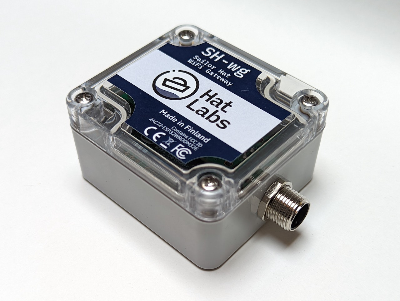
The Sailor Hat WiFi Gateway (SH-wg) allows you to connect WiFi devices to your boat's NMEA 2000 network. This lets you display your boat data on phones or tablets, extend the NMEA 2000 network wirelessly, or implement a bidirectional interface with Signal K marine data servers.
NMEA 2000 is a wired networking standard for marine electronics, and is used to connect boat sensor, control and display devices together. Examples include GPS, depth, wind speed, and engine sensors, autopilots as well as multi-function displays, also known as chart plotters.
Use cases of SH-wg include:
- Display your boat's data on a phone or tablet.
- Connect two network segments wirelessly using two SH-wg devices. For example, if you have 12V power cables pulled to your steering pedestal but have little room for pulling the NMEA 2000 cable required for new instruments, you can use two SH-wg devices to connect the steering pedestal devices to your main network.
- Connect your boat network wirelessly to a Signal K server, allowing advanced data processing and visualization.
SH-wg is open hardware and both the electronics hardware design files and software source code are available on GitHub for free download and customization.
SH-wg is available for purchase at the Hat Labs web store.
Trademarks
NMEA 0183 and NMEA 2000 are registered trademarks of National Marine Electronics Association. SeaTalk NG is a registered trademark of Raymarine UK Limited. WiFi is a registered trademark of the Wi-Fi Alliance. All other trademarks are the property of their respective owners.
Getting Started
Physical installation: Mounting and connecting to N2K
Find a suitable location for installing the SH-wg device. The following factors need to be considered:
- SH-wg must not be directly exposed to the elements. Installation in an instrument pod on the deck is fine but the device should be protected from direct rain or splash water.
- The device should be located close to the WiFi access point (if any) or to the client devices. The WiFi range in open air is up to 30m and the signal penetrates fiberglass well, but unnecessarily long distances may still cause communication problems.
- The device should not be placed in a metal enclosure; radio waves will not penetrate metal. Special attention to device placement and range should be paid with steel or aluminum boats.
- The device should be placed close to the NMEA 2000 network. The maximum allowed length of a drop cable is 6 m.
If you don't know much about NMEA 2000 or would like to have a refresher, have a look at the NMEA 2000 Primer before proceeding.
SH-wg can be connected to the NMEA 2000 network either using a standard drop cable or directly to a backbone T-connector.
If you decide to mount the device permanently, take a photo of the bottom sticker for future reference.
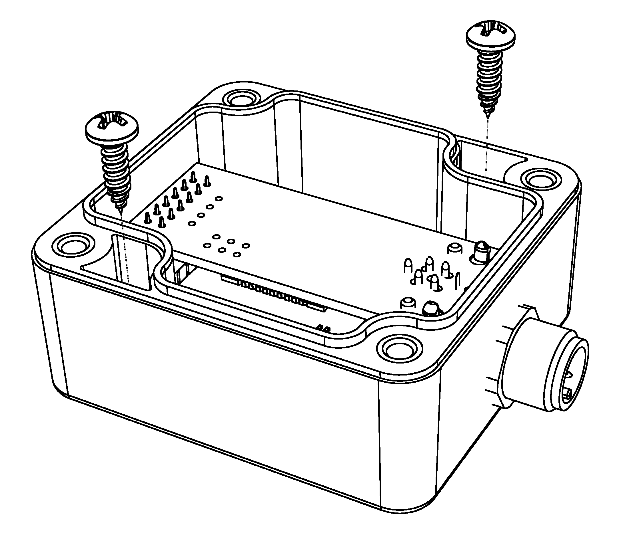
The device can be mounted on a surface with screws. Remove the lid temporarily and attach the device using two screws (3.5 mm or smaller) through the mounting holes.
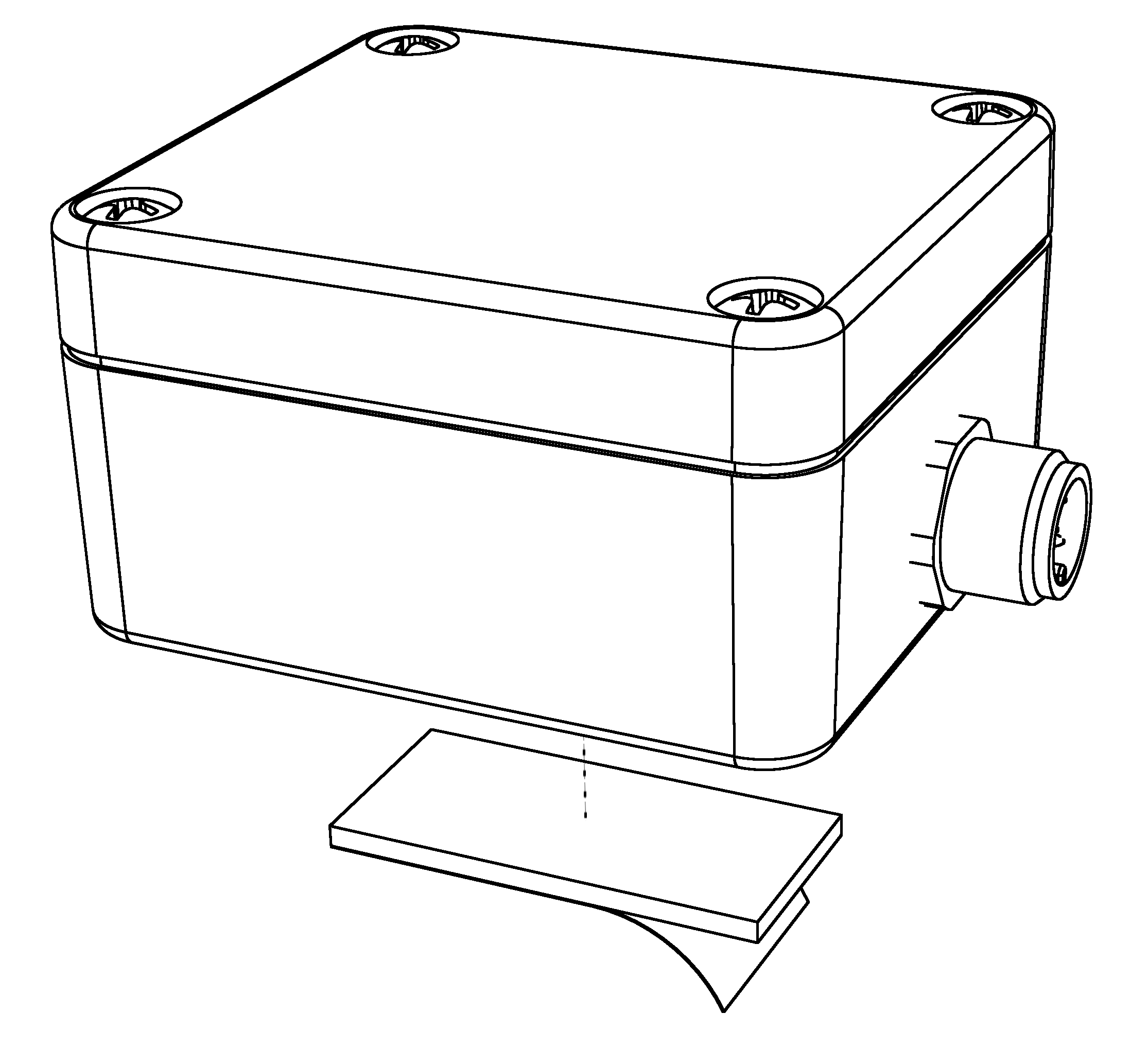
A piece of two-sided tape can also be used to attach the device on a surface.
Alternative mounting methods include zip-ties or just leaving the device hanging from the network T-connector.
WiFi Setup
SH-wg can be configured to create a WiFi access point of its own, or to connect as a client to an existing access point. These two setups are described in the figures below.
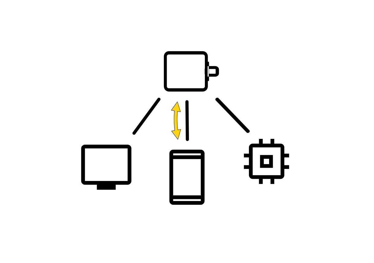
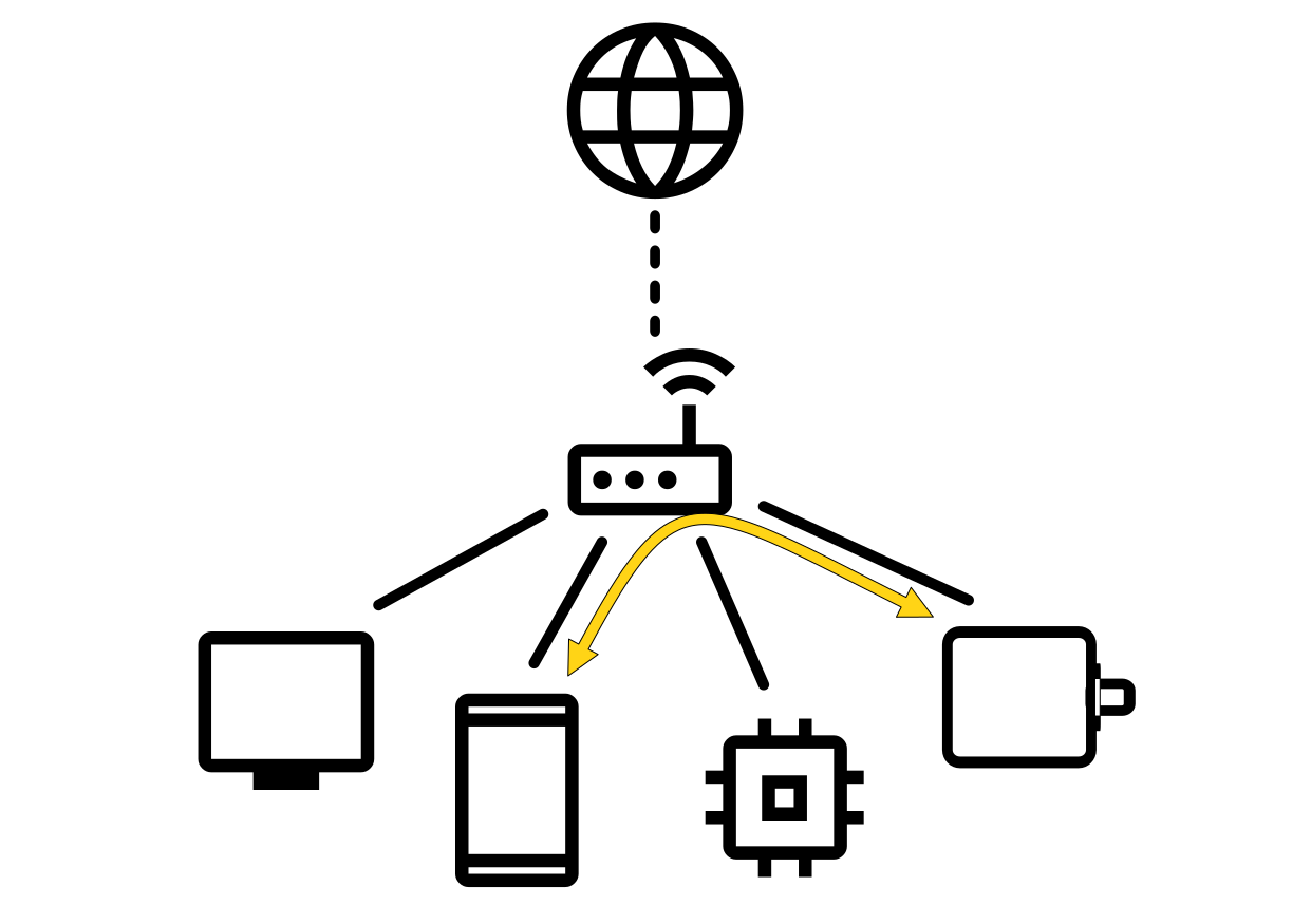
On left, we have a device working in access point mode. The client devices connect directly to this access point and communicate with it directly. Client devices can also communicate with each other via the SH-wg access point, albeit with a limited performance. No internet connectivity is provided to any of the devices. You can have a maximum of 4 simultaneous client devices connected at any time.
On right, we have a typical setup with a separate WiFi router device. The router creates its own WiFi access point and all client devices connect to it. Devices communicate with SH-wg via the access point. Internet connectivity can be optionally provided by the router.
Common Steps
An unconfigured SH-wg will create its own WiFi access point, a so-called "captive portal". The user can connect to the captive portal and set the WiFi configuration.
When the configuration portal is activated, the blue LED is blinking. The device is visible on the computer's WiFi network listing:
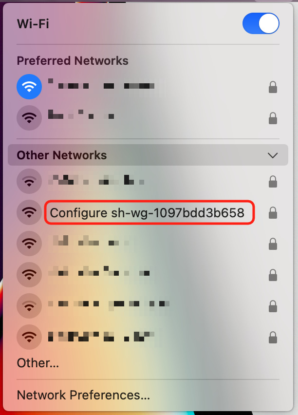
The network name is "Configure sh-wg-xxxxxxxxxxxx", the last 12 digits corresponding to the device unique identifier. When conneting to the captive portal, you also need to provide a password to connect to the configuration portal. The password is "abcdabcd". NOTE: This password is only used for connecting to the captive portal during the initial setup.
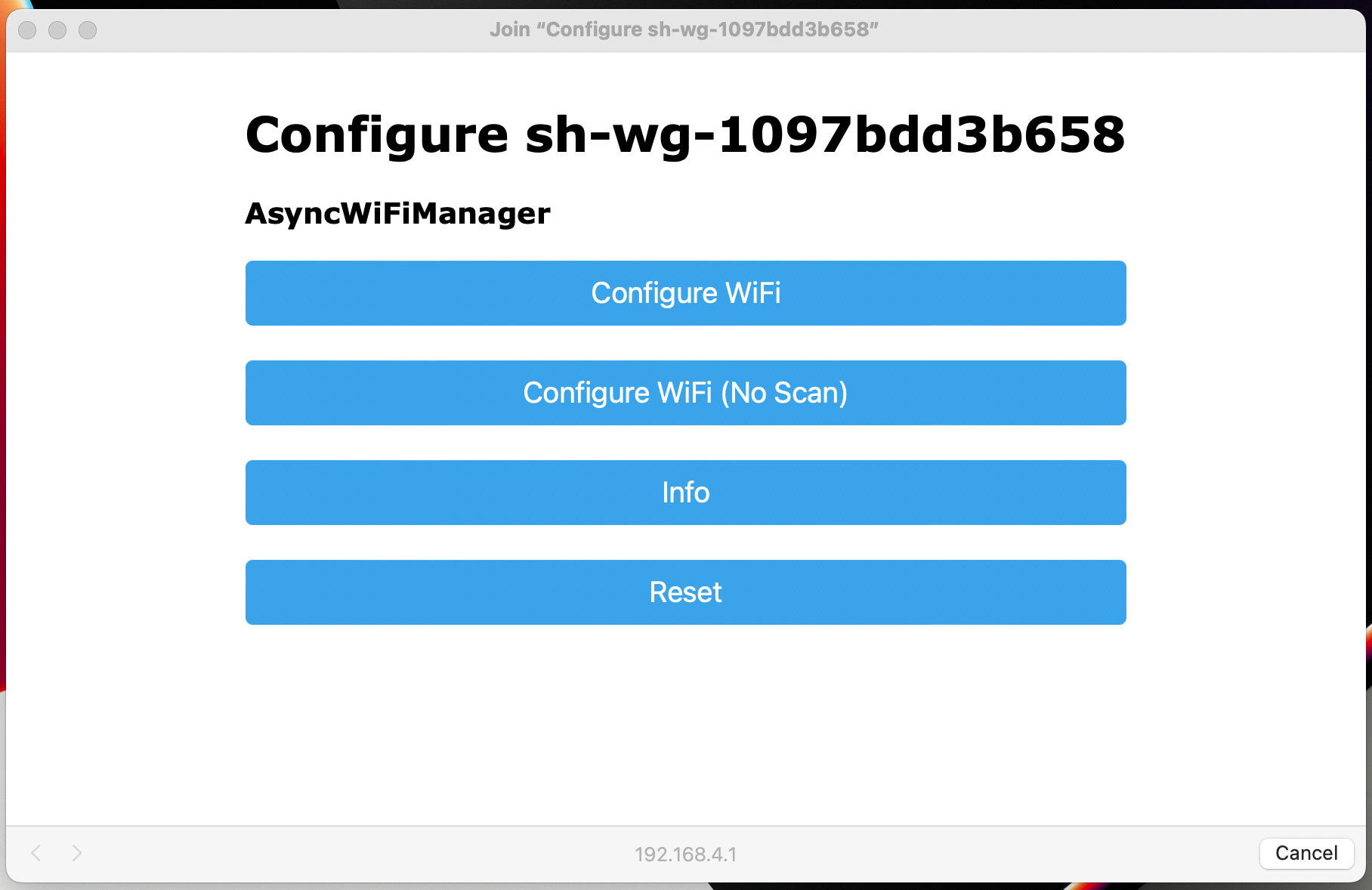
Once you have successfully connected to the configuration portal, you should be automatically presented with the WiFi configuration front page:
Configuring WiFi Client Mode
First, follow the steps in the "Common Steps" section above.
Click the "Configure WiFi" button. You'll get a list of nearby WiFi networks.
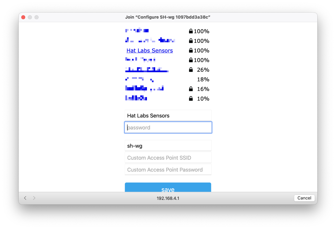
One of them should be the boat network you want to connect to. Select that and enter the network password. Press "save".
If the SH-wg is able to connect to the configured network, it will restart itself and the blue LED will stop blinking and turn on. If the configuration failed, the blue LED will keep blinking and you must repeat the operation.
Configuring WiFi Access Point
First, follow the steps in the "Common Steps" section above.
Click the "Configure WiFi" button. Now, ignore the list of WiFi networks. Instead, type in the desired WiFi Access Point name and password in the "Custom Access Point SSID" and "Custom Access Point Password" fields, respectively.
In the figure below, we have configured the access point name to be "My Access Point".
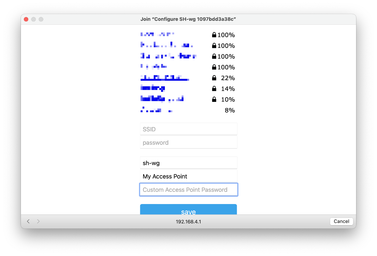
Click "save".
Changing WiFi Settings
Once the initial configuration has been performed, changing the WiFi settings can be performed in two ways. First, you can reset the device to factory defaults by following the instructions in the section below and then completing the initial setup again. Or, second, you can enter the device configuration page and update the settings there. This is described in Configuration.
Resetting the Device
If you ever feel you need to start over from the beginning, you can reset the device to factory defaults by using the provided magnet. Slide the magnet along the side of the device close to the green lights until the red power LED turns off. Keep the magnet there for 10 seconds (count slowly to 15 to be sure) and then remove it. The LEDs will flash and the blue LED will start blinking, indicating that the configuration access point is active. Follow the instructions in section WiFi Setup above to restart the initial setup.
Use Case: Transmit NMEA 2000 Data to Apps
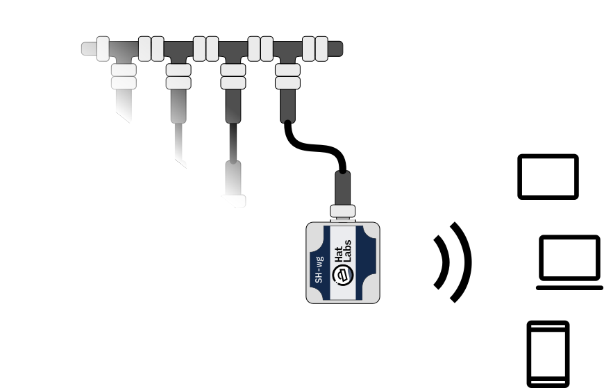
Transmitting boat device data to different wireless devices and apps is a common SH-wg use case. The WiFi may be configured either as a client or as an access point. In the default configuration, the device broadcasts NMEA 0183 sentences on UDP port 2000 and NMEA 2000 messages in YDWG RAW format on UDP port 2002. Many apps such as Navionics Boating, iSailor or OpenCPN can receive NMEA 0183 data as is, so no SH-wg configuration changes are needed. Some apps such as Boating pick up the transmissions automatically while others such as iSailor need to be configured to receive the data.
Use Case: Wireless NMEA 2000 Bridge
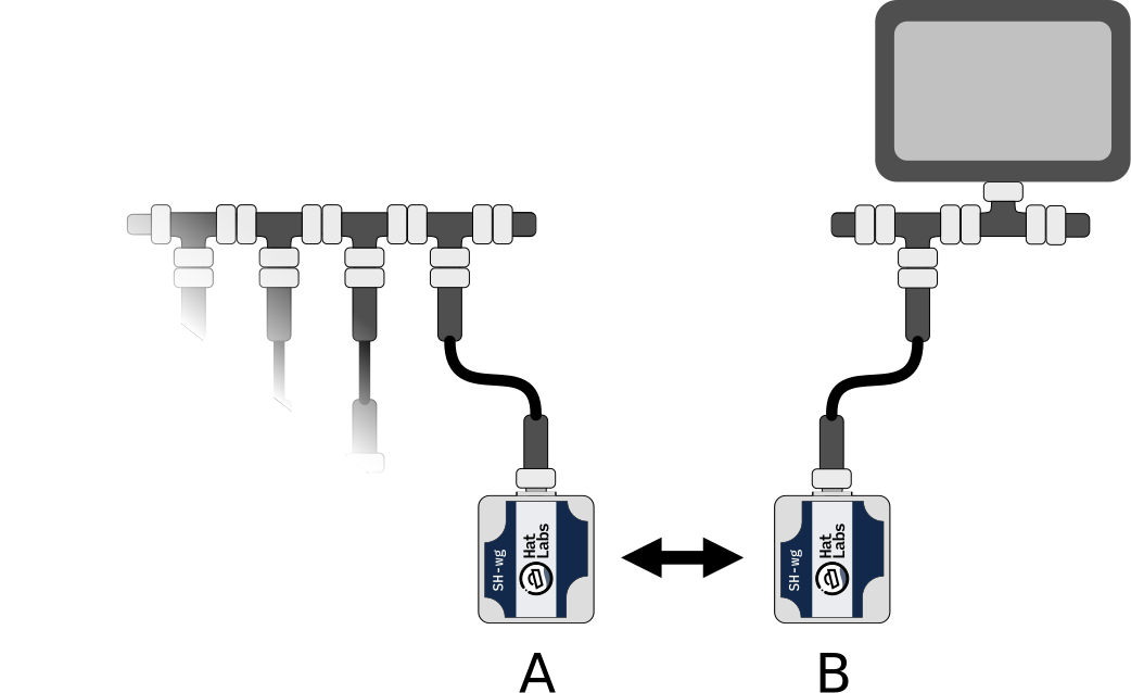
Two SH-wg devices can be used to create a wireless NMEA 2000 bridge. This setup is useful when the boat's NMEA 2000 network is not accessible from the desired location. For example, there might be a device pod in sailing boat cockpit with existing power wiring but no NMEA 2000 network. Or, on a motor boat, flybridge cable ducts might be insufficient for pulling new NMEA 2000 cabling. In these cases, a wireless NMEA 2000 bridge can be used to connect two separate NMEA 2000 network segments.
Two devices are needed. Let's call them device A and B.
Device A is connected to the existing NMEA 2000 network segment and configured as an access point.
The device should have a unique hostname.
sh-wg-a is used as an example.
The hostname can be configured either during the initial configuration or later via the configuration page.
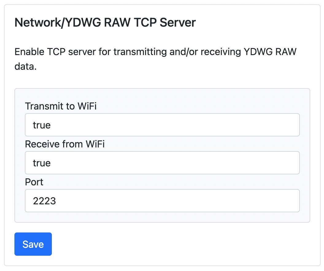
Device A should also have YDWG RAW TCP server configured to both Transmit and Receive.
Other transmission modes can be turned off or according to the user's needs.
A new NMEA 2000 network segment is created in the new location and device B is connected to it.
Device B is configured as a WiFi client to connect to the access point created by device A.
When setting up device B, unique hostname such as sh-wg-b should be used.
Next, the device B should be configured as a TCP client to connect to the YDWG RAW TCP server on device A.
The hostname of device A should be used as the server address.
If the hostname of device A is sh-wg-a, then the server address should be sh-wg-a.local.
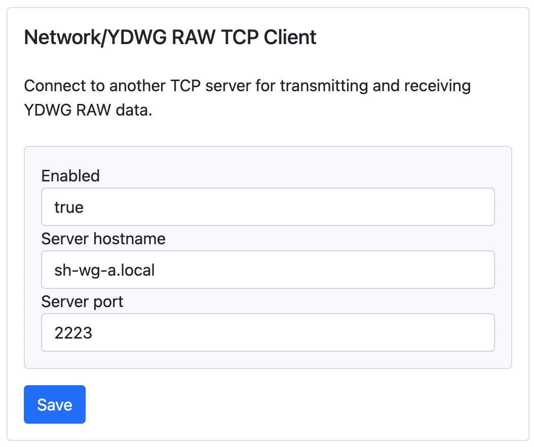
Now, restart the both devices. At this point, devices should pick up and forward each other's NMEA 2000 messages.
A wireless bridge is not limited to two SH-wg devices. Multiple client devices can be used to connect multiple NMEA 2000 network segments with each other.
Use Case: Wireless Signal K Interface
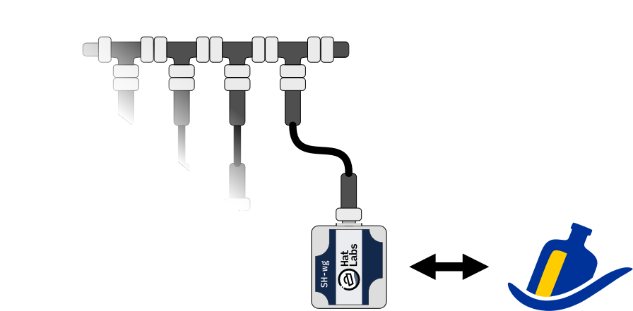
Signal K is an open data format and data exchange platform for marine use. It allows sharing data between different devices and apps and enables exciting features such as advanced visualization, data logging and connectivity to other open software such as OpenCPN, a popular open source chartplotter application.
SH-wg can be used to connect a NMEA 2000 network to a Signal K server. Configure the SH-wg device as a client to the WiFi network wo which your Signal K server is connected. Then, enable YDWG RAW TCP server with both Transmit and Receive on the device. Once you have done all this, click Save and restart the device.
Finally, connect the Signal K server to the data source. Open the Signal K server web user interface and navigate to "Server" -> "Data Connections". Click "Add" to create a new connection. Data Type should be "NMEA 2000". Enter "shwg" in the "ID" field. NMEA 2000 Source should be "Yacht Devices RAW TCP (canboatjs)". Click Apply and then restart the server by clicking Restart on the top right corner of the page. You should now see your new "shwg" data source in the Connection activity listing on the SK server Dashboard.
Configuration
Initial device setup is described in the Getting Started section. This section focuses on how to configure the device once it is up and running.
SH-wg is configured using a web interface.
If you are connected to the same network as the device, you can access the web interface by opening a web browser and navigating to http://sh-wg.local/.
Alternatively, you can enter the device IP address.
In access point mode, the device IP address is always 192.168.4.1.
In client mode, the device IP address is assigned by the router device via DHCP and usually can be found on the router configuration interface.
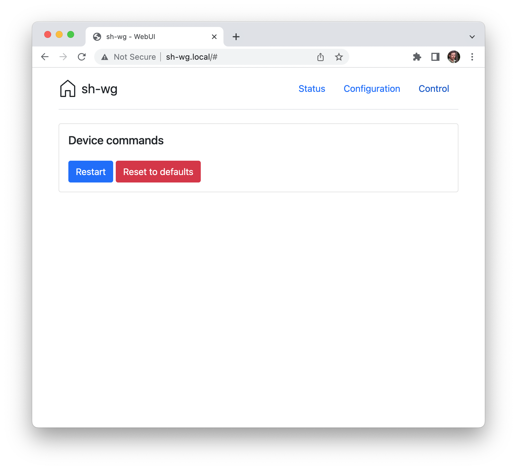
The web interface displays the Status page by default, as shown below. You can navigate to other pages using the top right menu.
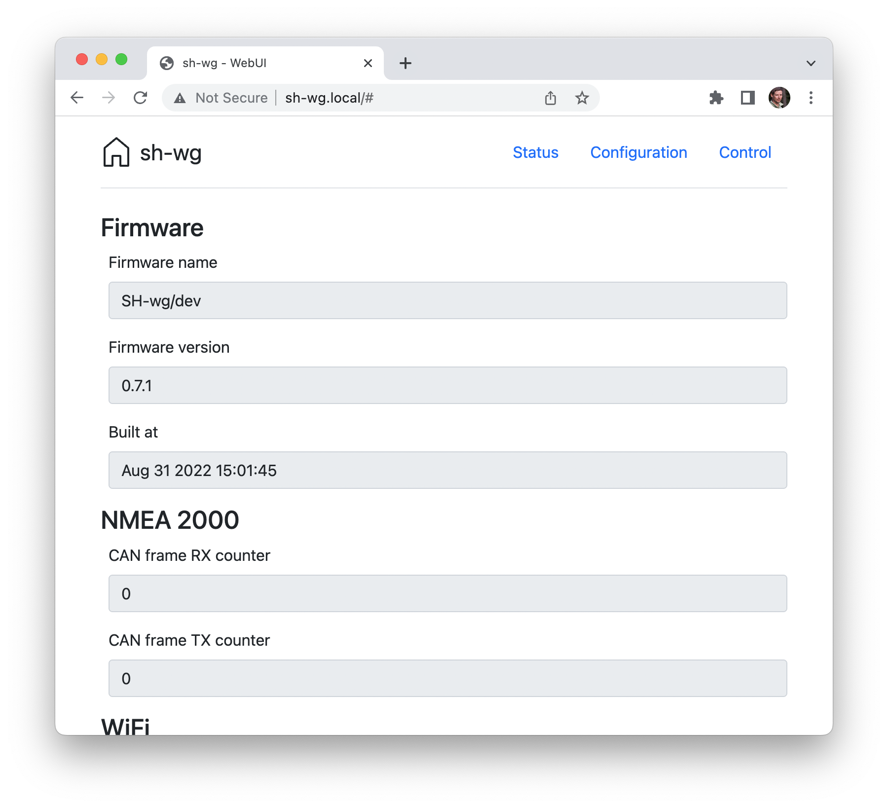
The Status page shows useful information on the device and its operation.
The Configuration page allows adjusting run-time configuration settings. Specific configuration options are described in the following sections. Note that when changing configuration settings, restarting the device is required for the changes to take effect.
Finally, the Control page allows controlling the device. At the moment, there are options only for rebooting the device and for resetting the device to factory defaults.
WiFi Configuration
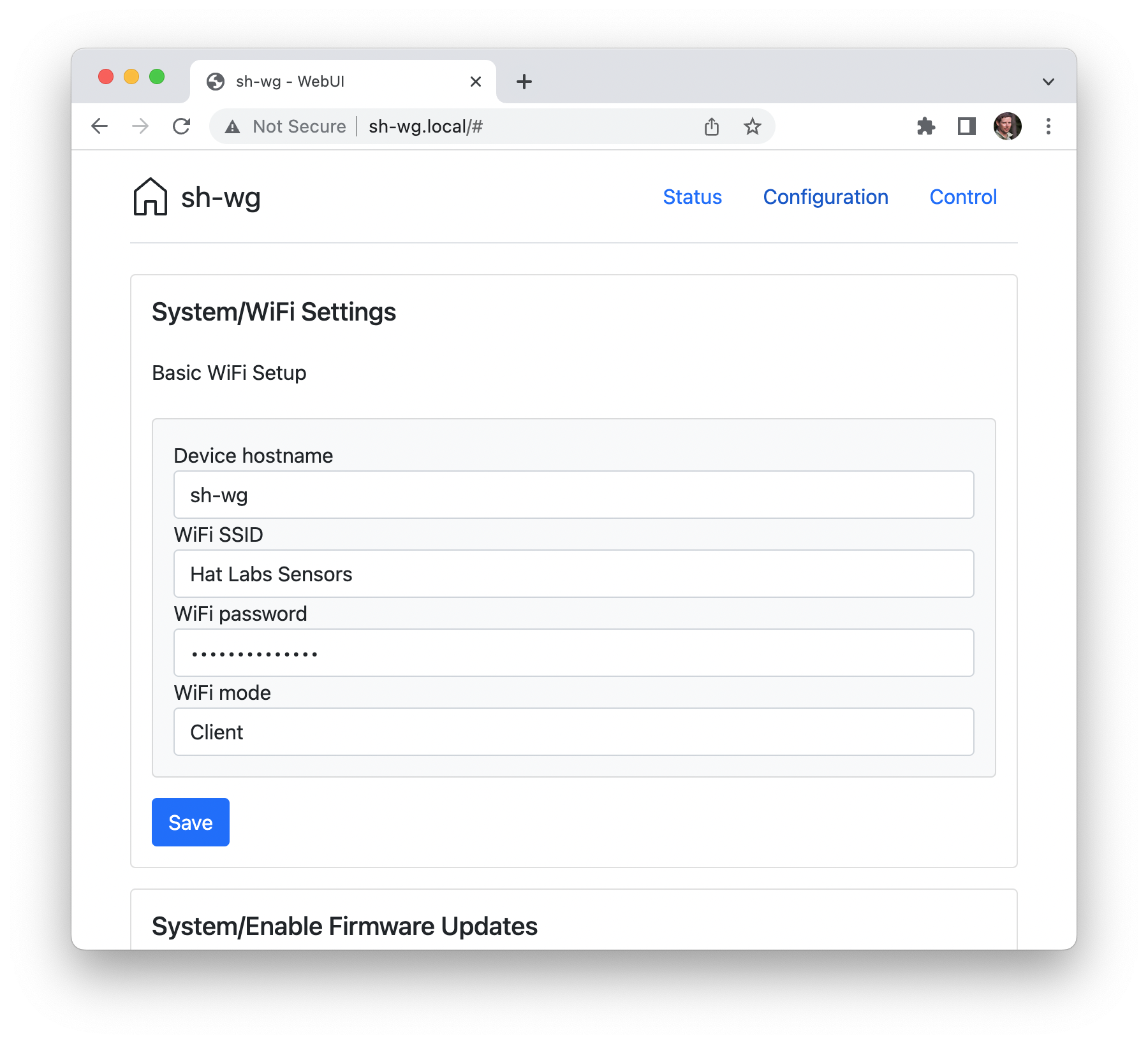
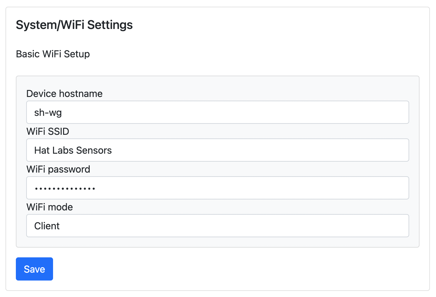
In the WiFi settings panel, shown below, you can adjust WiFi and network related settings.
The first box allows changing the device hostname.
This determines the mDNS hostname of the device, used for accessing the web UI.
The default value is sh-wg, corresponding to the mDNS hostname sh-wg.local.
The next three boxes allow changing the WiFi network settings. In client mode, the device connects to an existing WiFi network using the provided name and password. In access point mode, the device creates its own WiFi network using the provided name and password.
Firmware Update Configuration
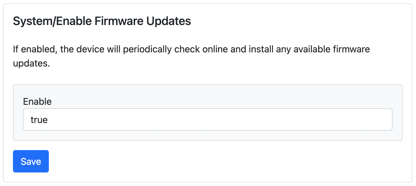
By default, the SH-wg device tries to check online for available firmware updates every now and then. If the device is connected to Internet and an update is available, it is downloaded and installed automatically.
If you would like to disable automatic updates, change the Enable Firmware Updates selection to False.
Protocol Configuration
Most panels on the Configuration page are dedicated to configuring the different data protocols supported by the device. The YDWG RAW UDP control panel is shown below.
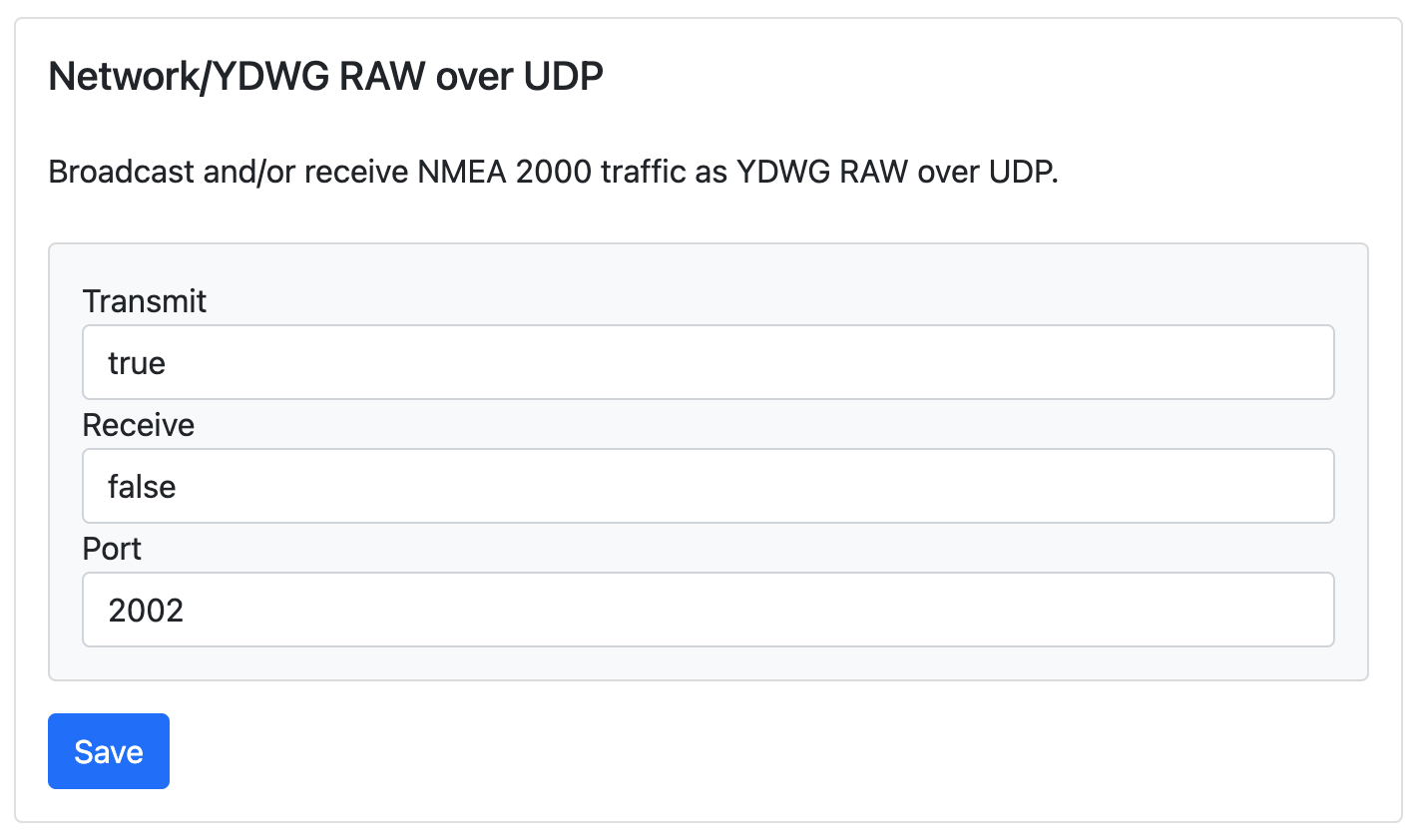
It allows you to enable or disable receiving and transmitting YDWG RAW data as well as setting a port number for the UDP socket.
Other panels allow configuring similar settings for the respective protocols.
Protocols and Data Formats
TCP and UDP
SH-wg supports data transmission both over TCP and UDP. TCP and UDP are standard Internet data transmission protocols. TCP is a connection-oriented protocol, meaning that a client such as a tablet or a phone must first establish a connection with the server (the SH-wg device) before any data can be transmitted. Establishing and maintaining a connection requires some additional processing overhead, but also guarantees that the data is delivered reliably. Additionally, the client device must know the hostname or the IP address of the server. When using TCP, no data is lost, and the data is delivered in the same order as it was sent. However, retransmission of lost packets can add some delay to the data stream.
UDP is a connectionless protocol, meaning that devices can send data to each other without first establishing a connection. No overhead is required to establish a connection, but data can be lost if the network is congested or the transmitting or receiving device is busy. Additionally, UDP supports broadcasting, meaning that data can be sent to all devices on the same network without any additional overhead. Listening devices just need to know the port number to listen to the traffic. SH-wg utilizes this feature for transmitting data in the local network.
Data Protocols
SH-wg is able to translate messages received over the NMEA 2000 network into NMEA 0183 sentences. The NMEA 0183 sentences are by default broadcast over UDP and also provided over a TCP server. The supported NMEA 2000 and NMEA 0183 sentences are listed in Specifications.
YDWG RAW is a open data protocol defined by Yacht Devices Ltd. for their YDWG-02 series of devices. It transmits raw NMEA 2000 messages over TCP or UDP with a simple encoding. SH-wg by default broadcasts the YDWG RAW protocol over UDP and serves it over TCP. Bidirectional use (both transmitting and receiving of messages) can be enabled in the configuration page for either protocol.
SeaSmart.Net is a data transmission protocol that encapsulates NMEA 2000 messages in NMEA 0183 sentences. The protocol can be enabled in the device configuration page. SeaSmart.Net uses the same ports as NMEA 0183.
The default ports for the different protocols are shown in the table below.
| Protocol | TCP Port | UDP Port |
|---|---|---|
| NMEA 0183 & SeaSmart.Net | 2222 | 2000 |
| YDWG RAW | 2223 | 2002 |
Hardware Description
The SH-wg enclosure is a polycarbonate box with a transparent lid. It has a single NMEA 2000 Micro-C connector that transmits both power and data.
The device includes multiple colored LEDs that indicate the status of the device. There is also a magnet sensor that detects the presence of a magnet. Both of these are described in sections below.
LEDs
The SH-wg device includes a number of LEDs that indicate the status of the device.
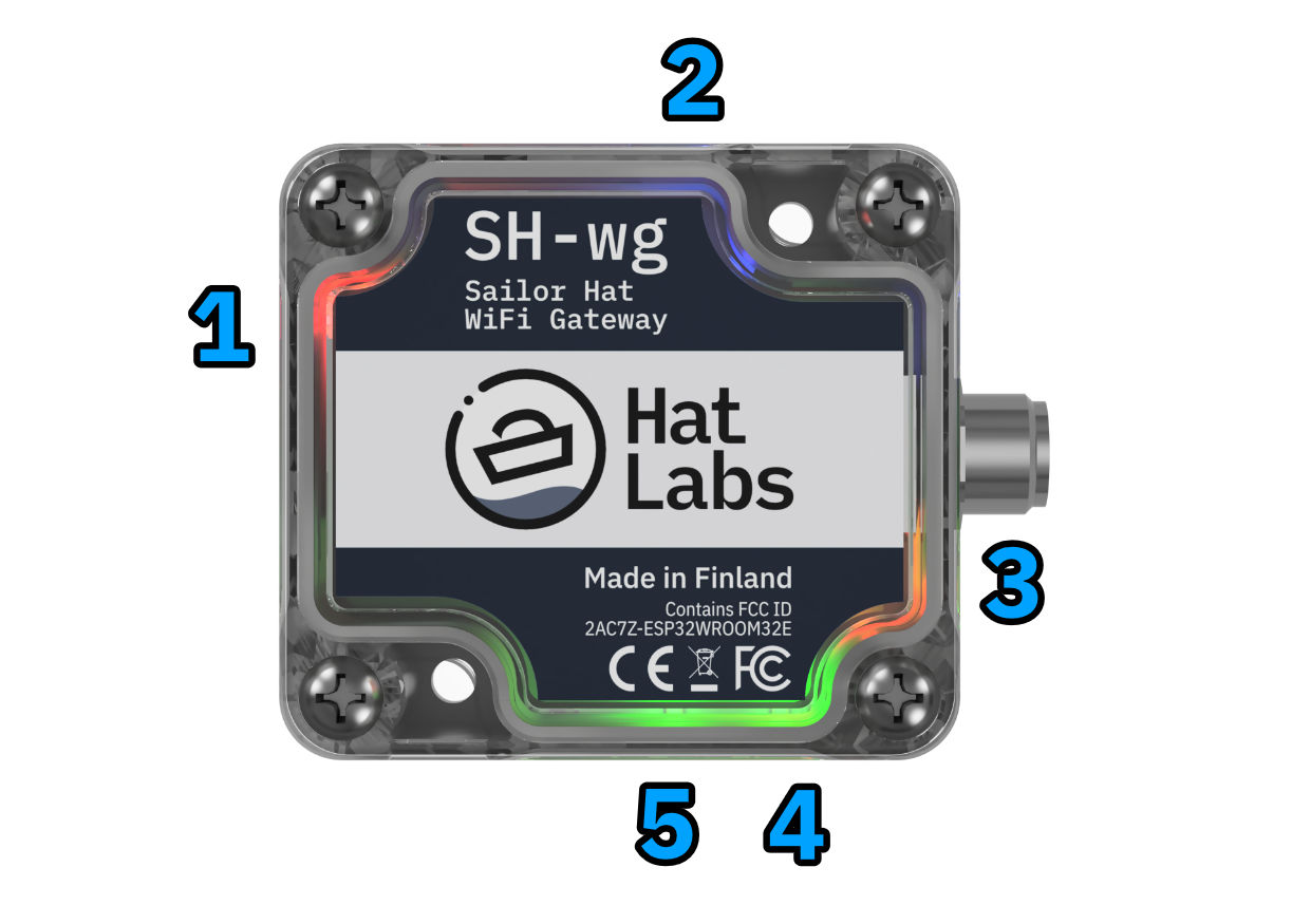
- Red: Power LED. On when the device is powered. Turns off when magnet presence is detected (see the next section). Blinks rapidly during an over-the-air update.
- Blue: WiFi LED. Flashes periodically when the configuration portal is activated. Flickers (turns briefly off) periodically when the device operates as an access point. On when WiFi is connected in client mode.
- Yellow: Normally on. Flickers when data is broadcast over UDP.
- Green: TX: Flashes when data is transmitted over the NMEA 2000 bus.
- Green: RX: Flashes when data is received over the NMEA 2000 bus.
Magnet "Push Button" Interface
To guarantee the integrity of the waterproof enclosure, basic interaction with the device is enabled using a magnet "push button" interface. Slide the provided neodymium magnet against the enclosure next to the magnet sensor shown in the picture below.
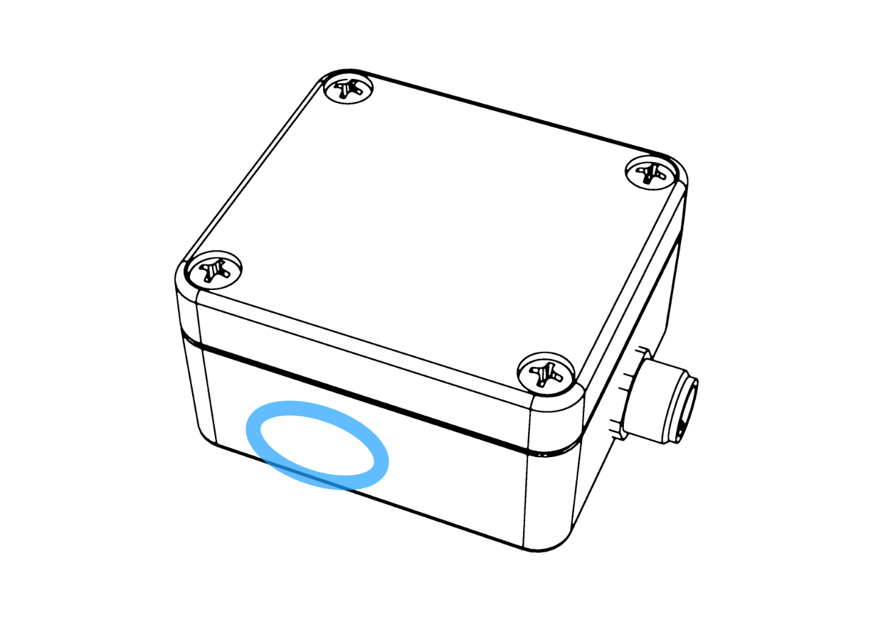
When the magnet is detected, the red LED turns off.
The sensor reacts to two different events:
- One second "button press": restart the device.
- Ten second long "button press": reset the device to factory defaults. This can be used to re-enable the configuration portal if the WiFi setup has changed and you are no longer able to access the device.
NMEA Primer
NMEA 2000 and NMEA 0183 are the most common standards for marine data transmission. They are used for transmitting data between sensors, chart plotters, autopilots, control units and other devices.
NMEA 0183
NMEA 0183, originally released in 1983 by the National Marine Electronics Association (NMEA), is an electrical interface and serial data protocol for transmitting data from one "talker" device to one or more "listener" devices.
The electrical standard used is RS-422, but most devices are also compatible with RS-232. The data rate is 4800 bps. NMEA-0183 does not define connectors. Instead, individual wires are typically connected to screw terminal blocks.
The data protocol is based on one-line text sentences. An example "Water speed and heading" sentence with both true and magnetic heading and speed in both knots and km/h is shown below.
NMEA 0183 is an aging standard with many limitations and being phased out in favor of newer standards, but it is still widely used. In particular, many devices use the sentence format for transmitting boat navigation data.
NMEA 2000
NMEA 2000, a communications standard originally published in 2001 by the National Marine Electronics Association, is a successor to NMEA 0183. It uses a Controller Area Network (CAN bus) as the electrical interface, with standardized cabling and connectors, and a data rate of 250 kbps. CAN bus is a vehicle bus standard universally used in the automotive industry, both in cars and in heavy vehicles. Each device on the bus can transmit and receive messages.
CAN bus transmits data in frames that have 64 bits of header information and up to 64 bits of payload. NMEA 2000 builds on the J1939 heavy-duty vehicle data protocol for defining a messaging format on top of CAN bus and adds some proprietary extensions for transmitting longer messages.
All NMEA 2000 networks consist of a backbone and one or more drop cables that branch off the backbone using T-connectors. Both ends of the backbone are terminated with a terminator. Additionally, the network must have a 12V power feed.
NMEA 2000 networks come in many different variants. "Micro" cabling with micro connectors is the most common for smaller boats, and is expected in this manual. Advanced installations may use mini or mid cables that have much larger diameter cables and heftier connectors. These allow for longer network installations without an excessive voltage drop. Furthermore, some vendor-specific variants exist as well. Raymarine's SeaTalk NG is probably the most common one. It uses proprietary connectors but is otherwise fully compatible with a standard NMEA 2000 network. Adapter cables can be used for connecting regular NMEA 2000 devices to a STNG network and vice versa.
NMEA 2000 starter kits, available from boat electronics suppliers, provide the necessary cables and connectors for building a small NMEA 2000 network. When adding devices to an existing network, a T-connector and a drop cable of appropriate length are needed.
The figure below shows a schematic illustration of a typical NMEA 2000 network.
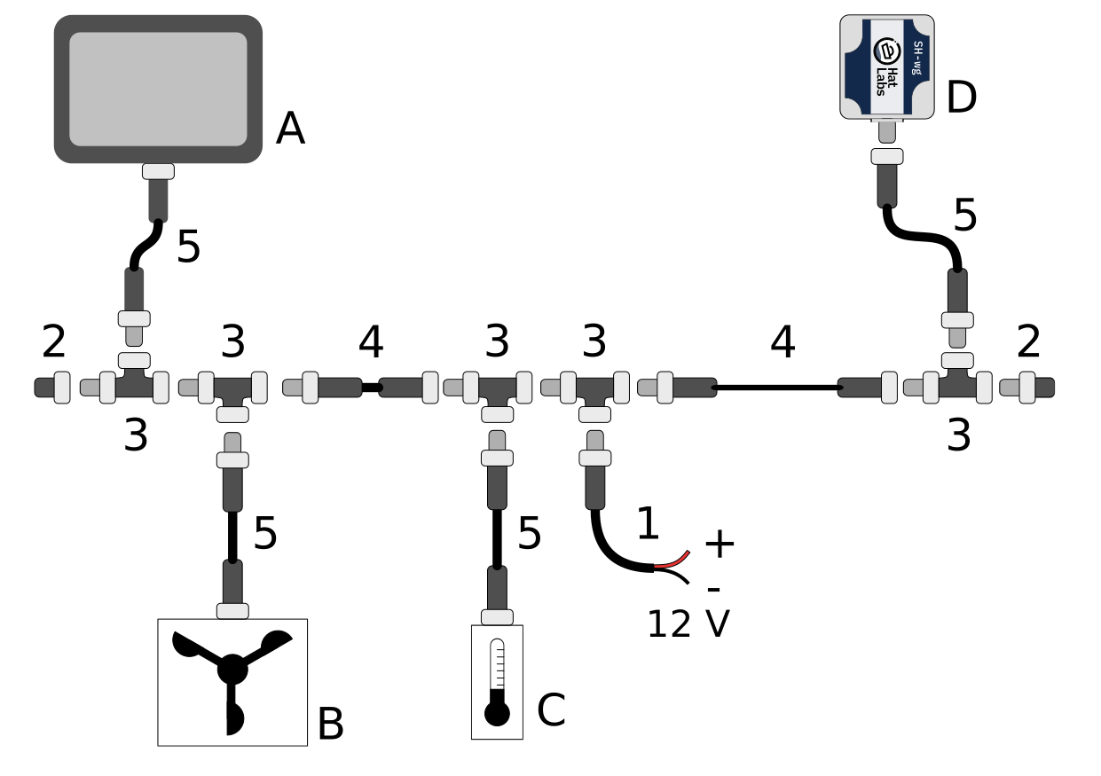
The figure components are:
- A
- A display device such as a Multi-function Display (MFD).
- B
- A wind sensor.
- C
- A temperature sensor.
- D
- A SH-wg device.
- 1
- N2K power cable. Every NMEA 2000 network segment must be connected to boat's 12 V power system. The power cable must be fused with a 3 A fuse.
- 2
- Network male and female terminators. The network backbone must be terminated with 120 ohm resistors for proper network operation.
- 3
- Drop cables are connected to the backbone using T-connectors. Special 4-way T-connectors are also available for connecting multiple devices to the backbone.
- 4
- Backbone cables extend the backbone. The maximum length of the network, measured from terminator to terminator, should not exceed 100 m.
- 5
- Drop cables connect individual devices to the backbone. The maximum length of the drop cable is 6 m.
Specifications
| Mechanical | |
|---|---|
| Dimensions, excluding connector (mm) | 64 x 58 x 35 |
| Weight (g) | 87 |
| Housing material | Polycarbonate |
| NMEA 2000 Connector | Micro-C |
| NMEA 2000 Connector Material | Nickel-plated brass |
| Environmental | |
|---|---|
| Environmental Protection | IP65 |
| Operating Temperature (°C) | -20 to +55 |
| Storage Temperature (°C) | -40 to +85 |
| Humidity (%) | 0 to 95 non-condensing |
| Electrical | |
|---|---|
| Supply Voltage (V DC) | 8-32 |
| Supply Current @ 12 V, typ. (mA) | 60 |
| Power Consumption, typ. (W) | 0.72 |
| Load Equivalence Number (LEN) | 2 |
| WiFi Radio | |
|---|---|
| Radio Module | ESP32-WROOM32 (datasheet) |
| Compatibility | IEEE 802.11 b/g/n |
| Bit Rate (Mbps) | up to 150 |
| Frequency Band (GHz) | 2.4 |
| Output power (dBm) | 20 |
| Approvals and Conformity | |
|---|---|
| General | CE |
| Standards | NMEA 2000 compliant WiFi compliant |
| Environmental | RoHS and REACH |
| RF module certification | CE (RED), FCC, IC, MIC, SRRC, KCC, NCC |
| Safety and health | Radio Equipment Directive (RED) 2014/53/EU, Art. 3.1.a EN 60950-1:2006 + A11:2009 + A1:2010 + A12:2011 + A2:2013 EN62311:2008 |
| EMC | Radio Equipment Directive (RED) 2014/53/EU, Art. 3.1.b EN 301 489-1 V2.2.3 EN 301 489-17 V3.2.4 |
| Spectrum | EN 300 328 V2.2.2 |
Supported NMEA 2000 PGNs
FIXME: Fill in
Hacking
SH-wg is open hardware and open software. You can customize the device software and even hardware to suit your needs. Programming pads are available on the top of the device for easy access to the microcontroller. Use an ESP-Prog board or other suitable programmer to program the microcontroller. For other use cases, JTAG pads and pads for 9 other GPIO pins are exposed on the main board for customization purposes.
We encourage you to share your customizations with other users on the Hat Labs discussion group!
Note that we are unable to provide individual support for software or hardware modifications, and any damage caused by such modifications is not covered by the warranty.
Support and Warranty
The Hat Labs discussion forum is the best place to ask questions and get help with SH-wg. By asking questions in the forum, you help other users as well.
Specific product support and warranty questions may also be sent to Hat Labs directly at info@hatlabs.fi.
Warranty
SH-wg is covered by a two-year warranty from the date of purchase. The warranty covers defects in materials and workmanship. The warranty does not cover damage caused by improper use or modification of the device.