Hardware Description
Tour Around the Board
Different functional blocks of the Sailor Hat for Raspberry Pi are described below.
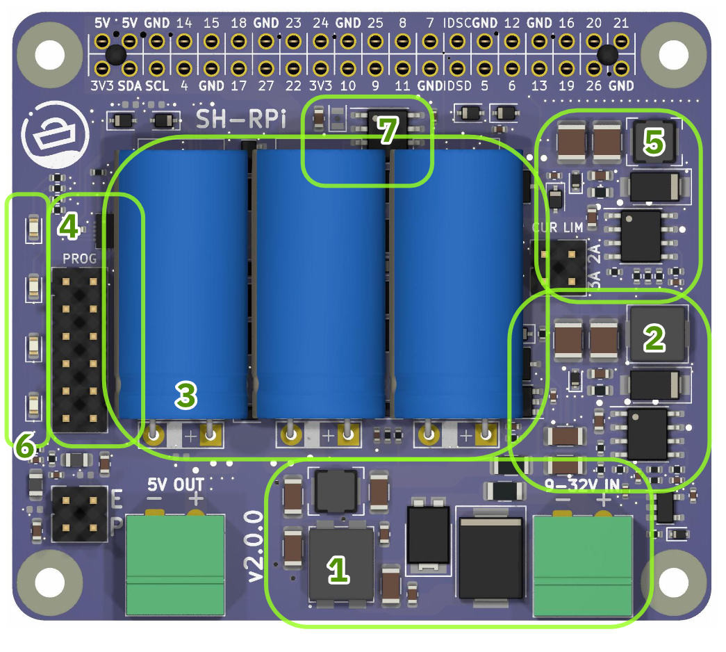
Functional blocks of the SH-RPi.
- Power input and protection.
Power input is provided through a Phoenix MC compatible 3.81 mm (0.15") pitch connector.
The permitted voltage range is 9-32V.
The protection circuitry at power input includes:
- 4 A SMD fuse
- 33 V transient voltage suppressor (5000W peak pulse power capability)
- Reverse polarity protection diode
- A choke and a pi-filter for controlling conducted electromagnetic interference
- First stage step-down (buck) converter with current limiting. The buck converter transforms the input voltage into an 8.8 V potential that the supercapacitor bank can handle. The step-down converter circuit also includes a separate current limiter that throttles the input current to 0.8 A (at the default setting).
- Three 20F 3.0 V supercapacitors. The supercapacitor bank acts as a power reservoir for the Raspberry Pi. It can power a Raspberry Pi 4B for up to 70 seconds (subject to the amount of additional peripherals, of course), and lower-power models for much longer. The supercapacitor also makes it possible to power the Raspberry Pi using a low-power interface such as the NMEA 2000 bus that limits the maximum individual node current to 1.0 A.
- Microcontroller.
The SH-RPi operations are controlled by an ATtiny1616 microcontroller.
The microcontroller performs the following functions:
- Measures the input voltage
- Measures the input current
- Measures the supercapacitor voltage
- Controls the status LED array
- Controls the 5V output
- Receives real-time clock interrupt information
- Communicates the SH-RPi status to the Raspberry Pi service over I2C
- Second stage buck converter. The buck converter converts the supercapacitor bank potential into the 5V Raspberry Pi input voltage. The maximum instantaneous output current capacity is 5 A, with at least 3 A attainable as continuous current without active cooling. The buck converter operation is controlled by the microcontroller. The microcontroller enables the boost converter when the supercapacitor voltage has risen above 8.0 V. During system shutdown or watchdog reboot, the microcontroller disables the boost converter to cut the Raspberry Pi input voltage.
- Status LED array. The four status LEDs indicate the board operational status LEDs as described in Section Status LEDs.
- Real-time clock. The board includes a PCF8563 real-time clock that can keep accurate time even in the absence of internet or GPS connectivity. The RTC communicates with the Raspberry Pi over I2C.
Connectors
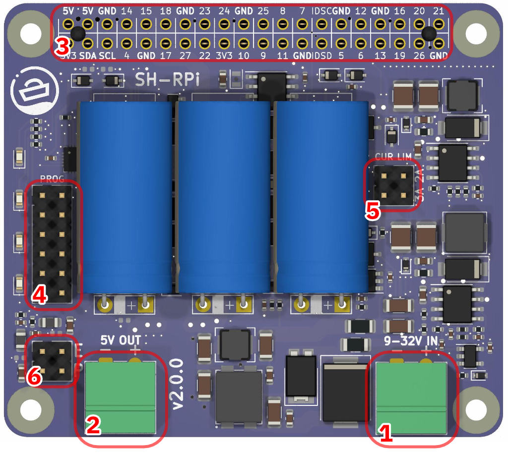
SH-RPi connectors, top side.
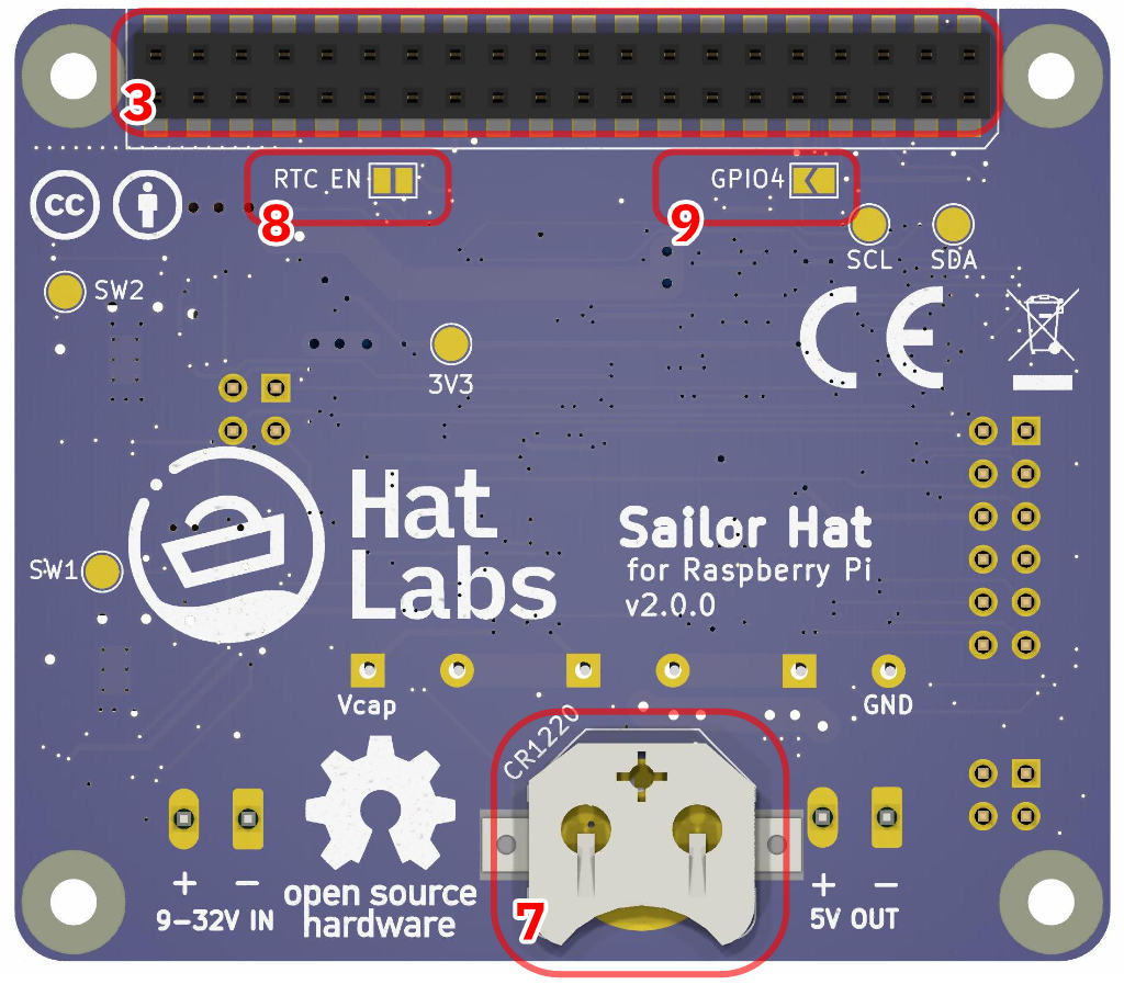
SH-RPi connectors, bottom side.
Power input connector.
The power connector is a Phoenix MC compatible 3.81 mm (0.15") pitch connector. The sales package includes a compatible screw terminal plug.
5V output connector. External 5V peripherals can be connected to this connector. The 5V output connector is a Phoenix MC compatible 3.81 mm (0.15") pitch connector as well.
Pass-through Raspberry Pi GPIO header. This is a standard 2x20 pin Raspberry Pi GPIO header. A provided stack-through connector should be inserted to connect the SH-RPi to a Raspberry Pi. Additional hats can be stacked on top of the Sailor Hat.
ATtiny1616 programming and debugging header. The header can be used to program the microcontroller with an external programmer or to enable onboard programming.
Current limiter header. Jumpers can be placed on the current limiter header to change the current limit setting to 1.8 A or 2.8 A (the default is 0.8 A). Place a jumper horizontally on the top row (labelled 2A) to set the current limit to 1.8 A. Place a jumper horizontally on the bottom row (labelled 3A) to set the current limit to 2.8 A.
External interrupt header. Not functional in v2.0.0 hardware.
CR1220 battery connector for real-time clock (on the bottom side). The real-time clock requires a CR1220 backup battery to keep time when the system is powered off. The battery must be oriented positive (flatter) side away from the board.
RTC Enable solder jumper. The Real-time clock is enabled by default. To disable the RTC, cut the traces between the solder jumper pads with a sharp knife. Be careful to not cut any nearby traces.
GPIO4 Enable. Connect the pads to connect Raspberry Pi GPIO4 to onboard microcontroller port PB5. This requires custom firmware functionality to be useful.
Power Supply
The SH-RPi includes an integrated power supply subsystem that provides a clean power supply to the Raspberry Pi from a noisy power source such as unregulated power supplies or a boat’s “house” battery system. The power supply permits input voltages between 9-32 V, although a potential less than 10 V will be regarded as an undervoltage situation to prevent deep-discharge damage to typical lead-acid batteries.
The operational diagram of the power supply subsystem is shown in the picture below.
The maximum input current is restricted to protect upstream power supplies and wiring. The default current limit is 0.8 A, but the limit can be increased to 1.8 A or 2.8 A by placing jumpers on the current limiter header.
The input voltage is stepped down by the first stage buck converter to charge the supercapacitor bank up to a voltage of 8.8 V. The supercapacitors are used to provide a power reservoir for the Raspberry Pi, both for short-duration glitches and to provide last-resort power during a system shutdown.
The second stage buck converter converts the supercapacitor voltage into the 5 V Raspberry Pi input voltage. The 5 V output is enabled by the microcontroller when the supercapacitor voltage is above 8.0 V and disabled when the supercapacitor voltage drops below 5.0 V. These limits can be configured by the user.
The maximum peak current output to the Raspberry Pi is 5 A. The maximum average current output is subject to the input current limiter setting and ambient temperature. At 0.8 A input current limit, the maximum sustained output current is about 1.4 A. At 2.8 A input current limit setting, the maximum average output current is limited by the system thermal characteristics. In an open space at room temperature, the maximum average 5 V output current is at least 3.0 A. Higher values are possible with active cooling of the SH-RPi board.
At 1.4 A output current, the total power supply efficiency is 79%.

Power supply operation diagram with example current and voltage values.
Status LEDs
The SH-RPi LED array at the left side of the board is used to indicate the operational status of the board. The bar display indicates the charge state of the supercapacitor bank. The first LED begins to light up when the voltage is above 5 V and all LEDs are fully lit at 9 V supercapacitor potential.
Overlaid on the bar display, different blink patterns indicate the state of the board as follows.
| Pattern | Description |
|---|---|
| No blinking | Charging/normal operation (1) |
| Short blip off every 4 s | Watchdog active (2) |
| Roll to left | No input voltage (3) |
| Two blips off with 1 s pause | Shutting down (4) |
| Two blinks on with 2 s pause | Sleeping (5) |
| Alternating LEDs blinking | Watchdog reboot (6) |
| Rapid blinking | Fault - contact manufacturer (7) |
Detailed description of the states follows:
- The supercapacitors are charging and if the supercap voltage is above 8.0 V, the 5 V output is enabled. The Raspberry Pi OS daemon is not active.
- The daemon is active and the watchdog is enabled. The operating system has started up and is running normally.
- Power input is lost and the supercapacitors are depleting. The 5 V output is enabled.
- The daemon has initiated a shutdown. The SH-RPi is waiting for the Raspberry Pi to shut down.
- The SH-RPi is in a sleep state. The 5 V output is disabled and the board is waiting for a real-time clock alarm to wake up.
- SH-RPi did not receive a heartbeat from the daemon for 10 s, suggesting that the Pi has crashed. The Raspberry Pi is reset by turning 5 V off for two seconds.
- The SH-RPi has detected a supercapacitor overvoltage condition. Contact the manufacturer for further assistance.
Watchdog Reboot Functionality
In addition to the power supply, the Sailor Hat for Raspberry Pi incorporates a hardware watchdog timer that can be used to reboot the Raspberry Pi in the case of a software or hardware lockup. The watchdog timer is enabled by default and can be disabled by applying the command shrpi set watchdog 0 on the device command line if needed. When enabled, the watchdog timer will restart the Raspberry Pi if it doesn’t receive a “heartbeat” signal from the Raspberry Pi within a predetermined time interval (typically 10 seconds).
The Raspberry Pi must run a service that sends a periodic heartbeat signal to the SH-RPi. The service can be installed from the provided software package.
If the watchdog timer triggers a reboot, the SH-RPi will disable the 5V output for a short period to force a Raspberry Pi restart. The SH-RPi will then re-enable the 5 V output to allow the Raspberry Pi to boot up again.
Real-Time Clock
The SH-RPi includes a PCF8563 real-time clock (RTC) that can provide accurate timekeeping even when the Raspberry Pi is not connected to the internet or a GPS signal is not available. The RTC is connected to the Raspberry Pi via the I2C bus.
To use the RTC, a CR1220 backup battery must be installed on the bottom side of the board. The positive side (the flatter side) of the battery should be facing away from the board.
When using the SH-RPi board with a built-in RTC, the RTCs may have conflicting I2C addresses. In such a case, the RTC on the SH-RPi can be disabled by cutting the traces between the RTC EN solder jumper pads.
Hardware Configuration
The Sailor Hat for Raspberry Pi can be configured by the user to adapt to specific use cases. Configuration options include:
- Current limiter setting. The input current limiter can be set to 0.8 A (default), 1.8 A, or 2.8 A by placing jumpers on the current limiter header.
- Real-time clock enable. The RTC can be enabled or disabled with a solder jumper.
- GPIO4 enable. Connect the pads to connect Raspberry Pi GPIO4 to the onboard microcontroller port PB5. This requires custom firmware functionality to be useful.
I2C
Sailor Hat communicates with the Raspberry Pi using I2C bus 1 on GPIO pins 3 and 5. (GPIO2 and GPIO3, respectively). The I2C address is 0x6d.
The PCF8563 real-time clock additionally reserves the I2C address 0x51 on the same bus.