Getting Started
Hardware Assembly
SH-RPi is delivered fully assembled. The hardware installation steps are:
- Insert the 40-pin stackthrough header into the SH-RPi through the socket on the bottom side, pins facing upwards.
- Plug the SH-RPi onto the Raspberry Pi GPIO header (optionally using the hex standoffs).
- Attach appropriate power wires to the terminal plugs. The terminal plugs arrive with the screws tightened, so ensure you loosen them before inserting the wires.
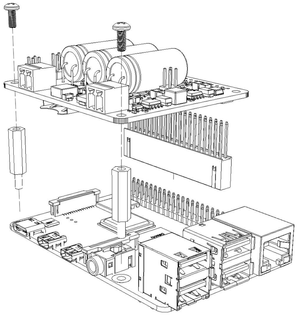
Hardware assembly diagram for SH-RPi v2.0.0.
Power Connection
Warning
Never connect the power input to the 5V output connector! Doing so will permanently damage the Raspberry Pi and the SH-RPi.Connect a 10-32 V power source to the SH-RPi power input connector as shown in the following figure.
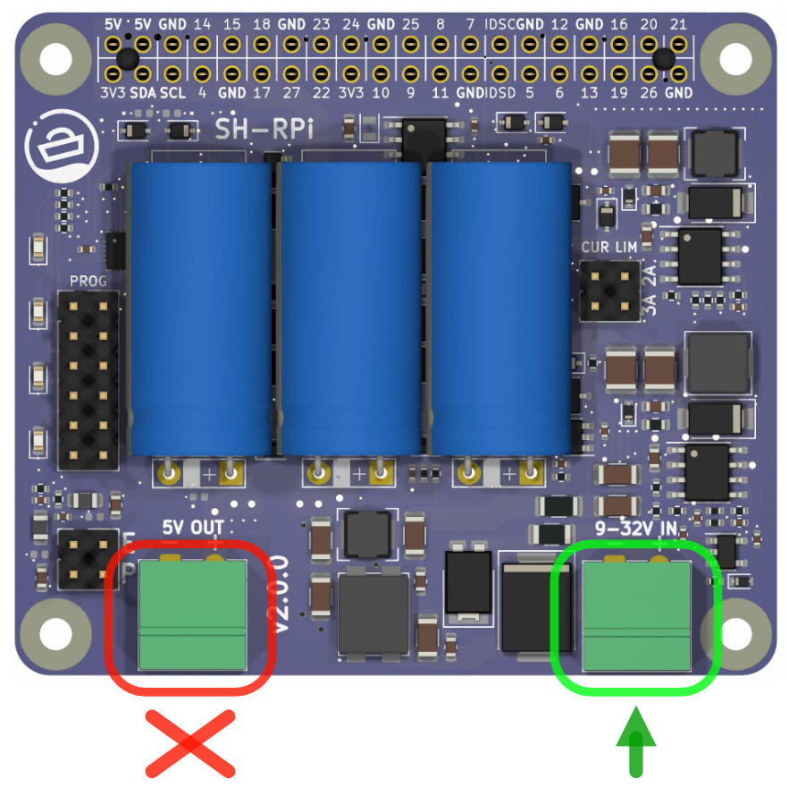
Connect the power source to the connector circled in green.
The power source must be rated for at least 1.0 A current at the specified output voltage. All things being equal, a power supply with a higher output voltage, such as 24 V, will result in slightly more efficient operation. Otherwise, 12 V power systems on boats and vehicles, or DC power sources, work well.
Software Installation
Additional software is required for the Raspberry Pi OS to run the system service that will automatically initiate system shutdown when power is cut. An automated installation script is provided to simplify the installation process.
Automated Installation
An automated installation script is provided. The script is tested on newly flashed Raspberry Pi OS and may fail on heavily modified systems. Installation has not been tested on other operating systems.
To run the automated installation script, copy and paste the following command onto the Raspberry Pi command prompt:
curl -L \
    https://raw.githubusercontent.com/hatlabs/SH-RPi-daemon/main/install-online.sh \
    | sudo bash
The command spans three lines, and when you paste it into your terminal window, it may display line continuation characters. That’s okay. Press “Enter” to run the command.
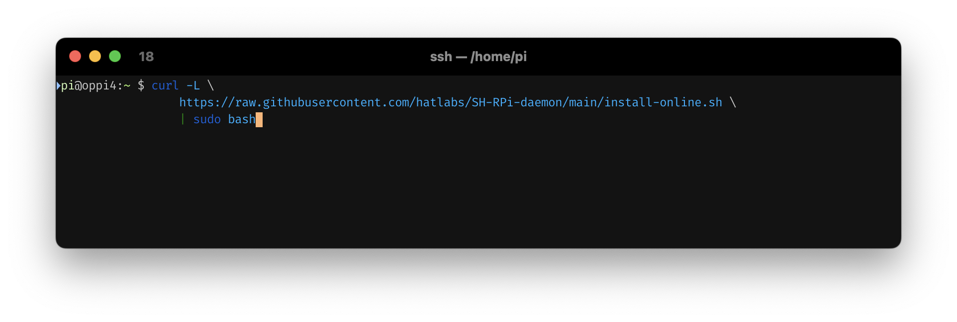
Installation command in terminal
The command will fetch the installation script and execute it automatically.
The automated installation script will:
- enable the I2C interface, required for the SH-RPi to communicate with the Raspberry Pi
- if support for the NMEA 2000 interface add-on card is selected
- enable the SPI interface and a device overlay
- define the CAN network interface
- if support for the NMEA 0183 interface add-on card is selected
- enable the SPI interface and a device overlay
- enable the device overlay for the real-time clock
- if support for the MAX-M8Q GNSS HAT is selected
- enable the serial UART interface
- disable the serial console
- disable Bluetooth as it conflicts with the serial UART interface
- install the SH-RPi service software
Enclosures
If you plan to use your Raspberry Pi and SH-RPi outdoors, in a vehicle or on a boat, or in highly condensing environments, always place the device in a waterproof enclosure! Hat Labs offers a variety of waterproof enclosures.
The medium and large enclosures come with a perforated base plate and mount adapters that can be used to mount the Raspberry Pi, additional HATs and other components. Other enclosures are provided with 3D printed sticker mounts.
Medium Enclosure Build
The medium size enclosure is designed to fit the Raspberry Pi 4 Model B, the SH-RPi and multiple HATs in a vertical orientation. Installation is described below.
Assembly
We start with a bare enclosure, shown in the following figure.
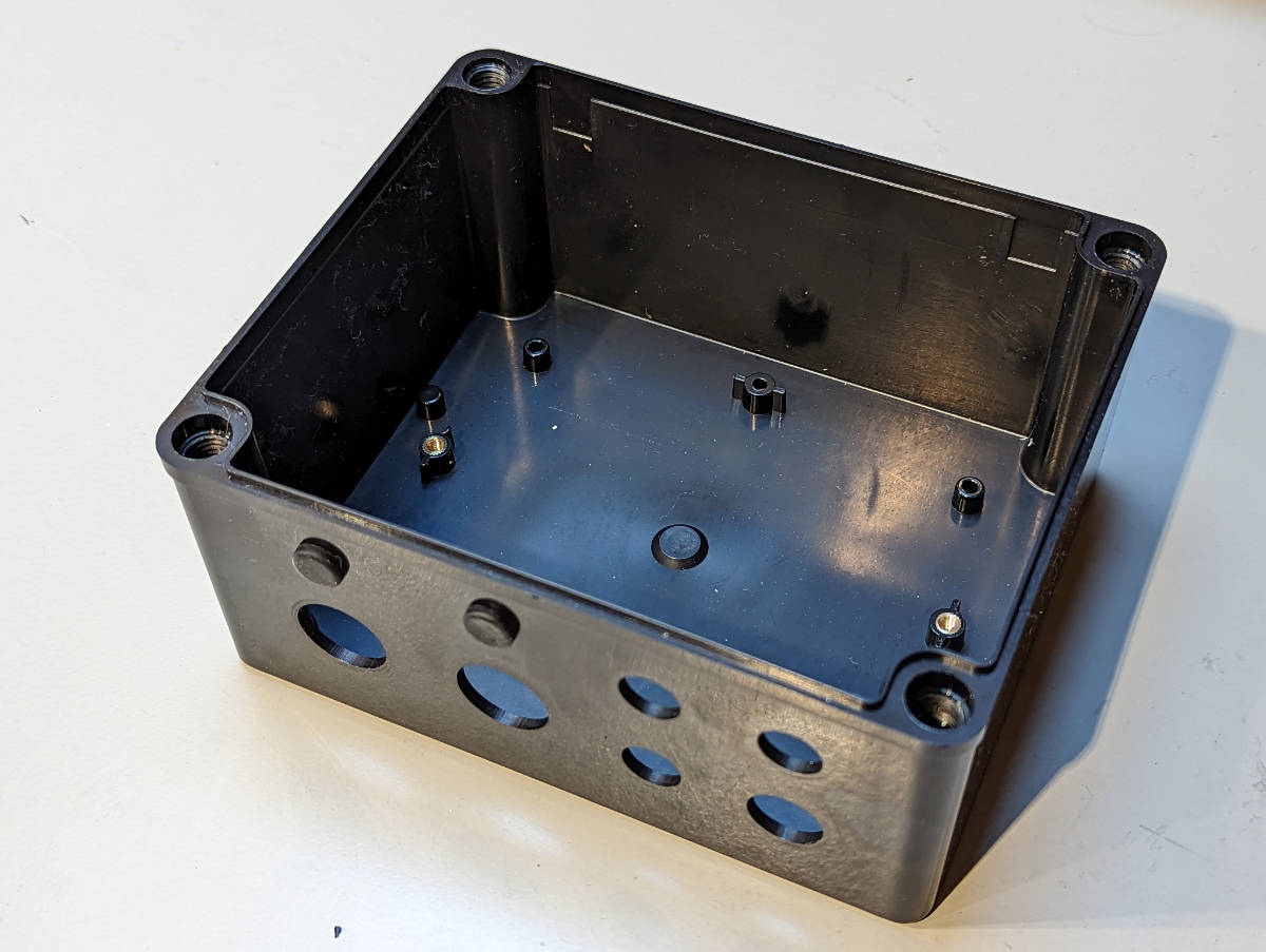
Enclosure without any of the components.
First, install all connectors you need. Before installing the connectors, you may need to solder wires to them. Soldering instructions for cup terminals can be found in this YouTube video:
There is no real standard for the power connector pinouts, but we suggest to always connect GND to pin 1 and +12V/24V to pin 2. The following figure shows the power connector installed.
Then, insert the connectors into the enclosure. The following figure shows the connectors installed.
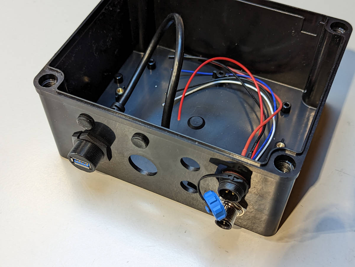
Connectors installed.
If the enclosure is to be used in a condensing environment such as on a boat or outdoors, seal the remaining holes with plugged cable glands. The following figure shows how the plug should be installed in the cable glands.
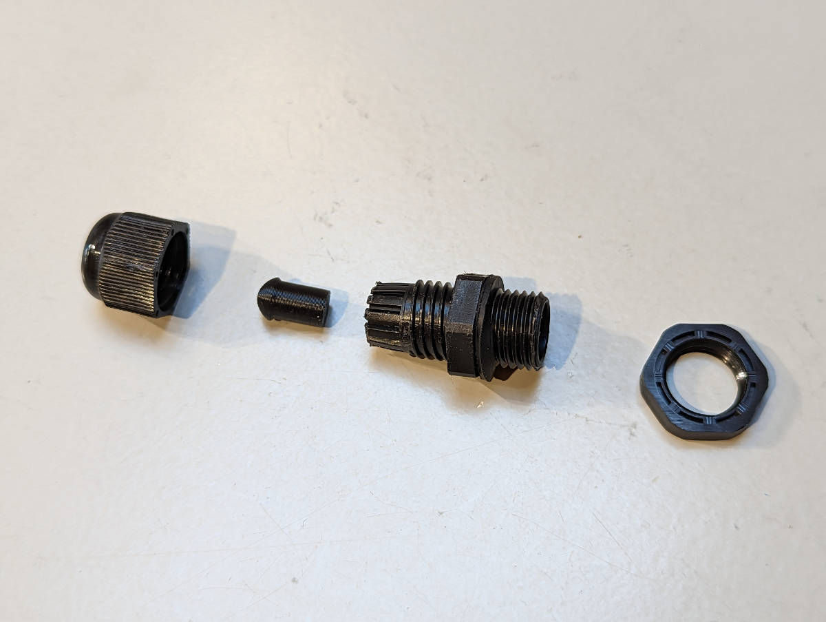
Cable gland plug.
And the following figure shows the cable glands installed. This makes the enclosure waterproof.
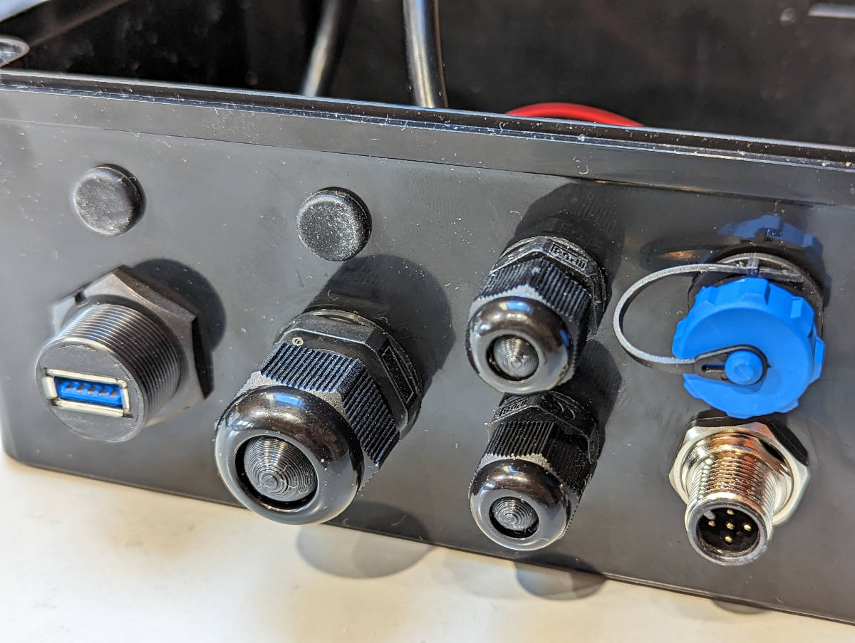
Cable glands installed.
Next, we take the parts we want to install in the enclosure and place them on the base plate. The following figure shows the parts we will install. The black plastic parts are the vertical mounts that hold the PCB stack in place.
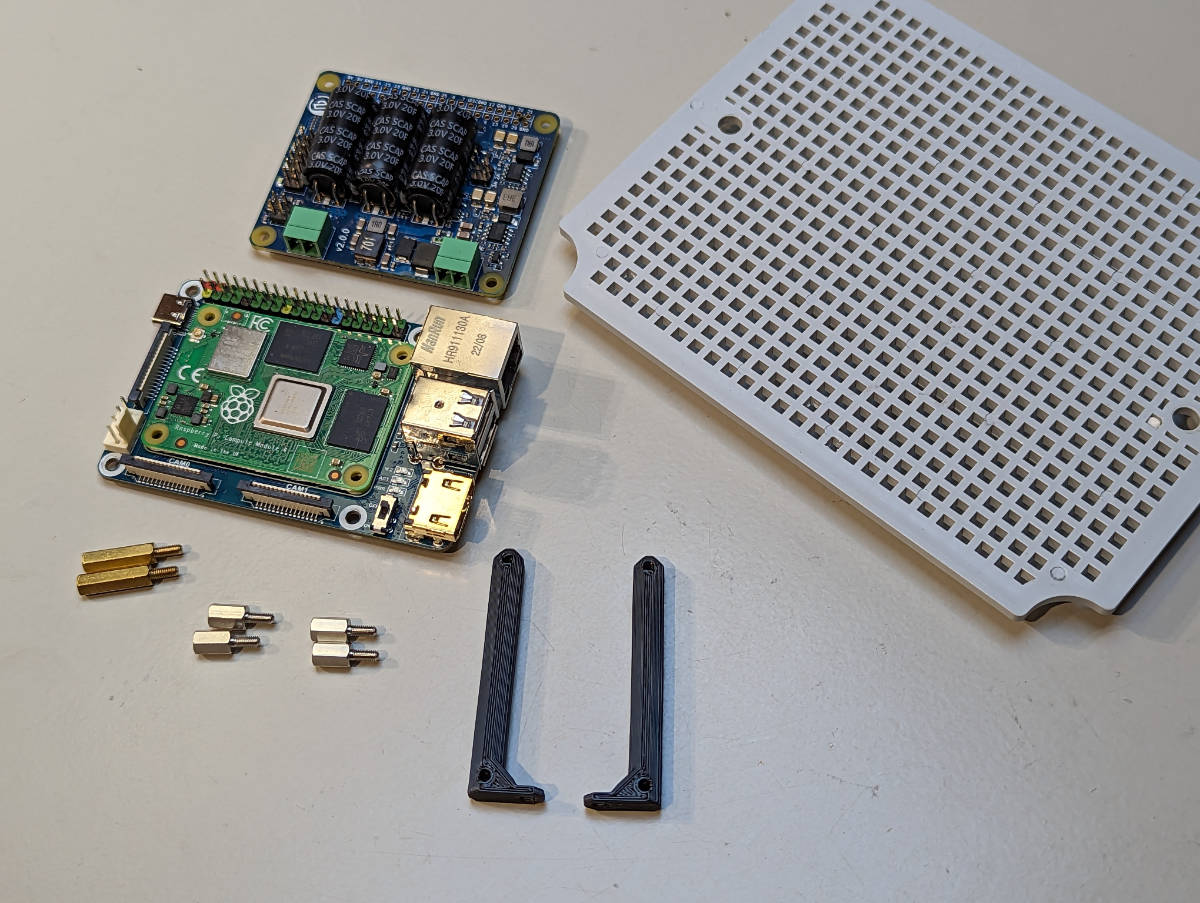
Ingredients.
First, the 6mm hex standoffs are screwed into the vertical mounts. Hand tigthen only!.
The following figure shows the vertical mounts with the standoffs installed.
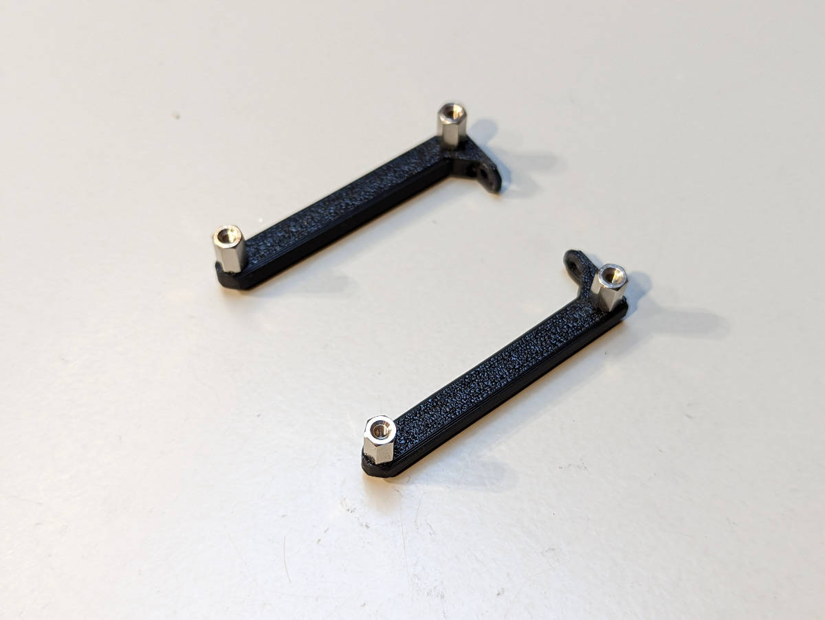
Vertical mounts with hex standoffs.
You can then attach the mounts to the Raspberry Pi or the base board. Use the M2.5 screws to attach the board next to the GPIO pins and the M2.5 16mm hex standoffs on the opposite side.
Next, we install the stack-through header onto the SH-RPi. Press gently and evenly to avoid bending the pins. The optimal header height depends on the HAT ordering. If you insert the SH-RPi directly on top of the Raspberry Pi, remove the spacer from the stack-through header. On the other hand, the spacer is needed if you install the SH-RPi on top of another interface HAT.
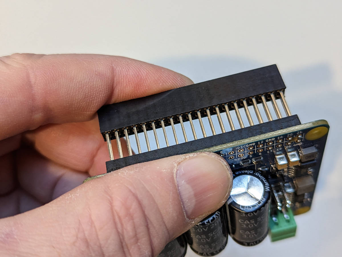
Inserting the stack-through header.
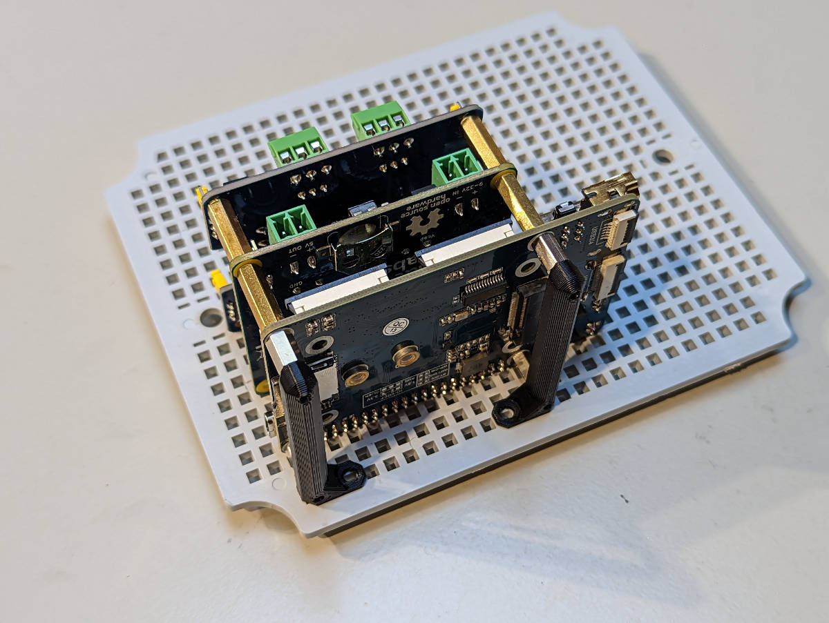
The next figure shows the SH-RPi mounted on the base board.
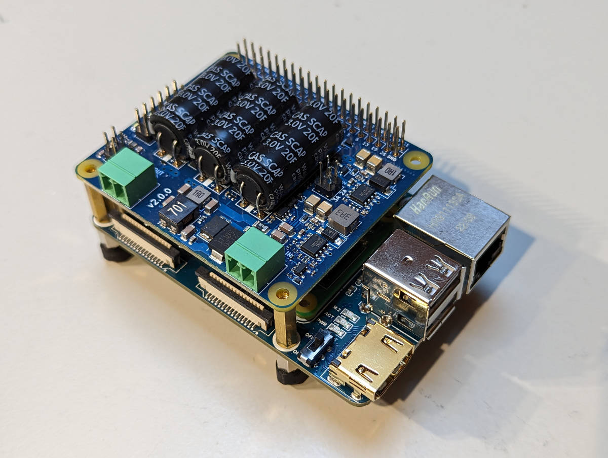
SH-RPi mounted on the base board.
Power Wiring
In this walkthrough, we will also install an additional CAN HAT for NMEA 2000 connectivity. The following figure shows the CAN HAT mounted on the SH-RPi.
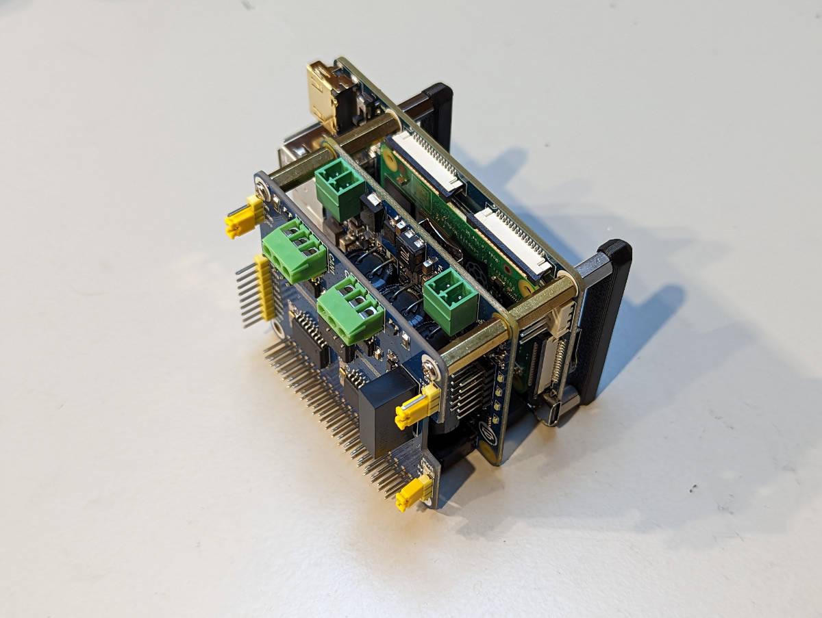
CAN HAT mounted on the SH-RPi.
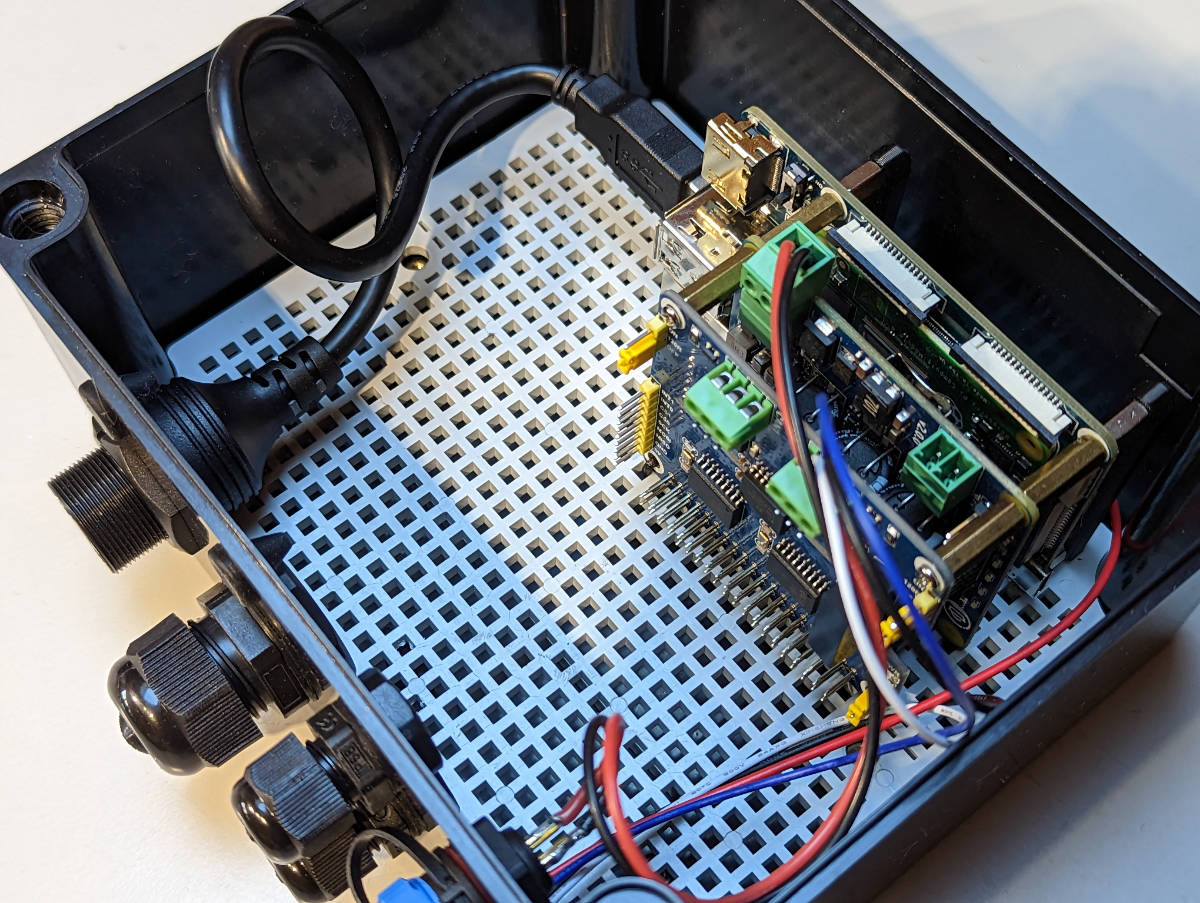
The next step is to install the PCB stack on the base plate. Use the provided M3 screws to secure the stack in place. Do not overtigthen the screws.
PCB stack installed on the base plate.
Next, strip the connector wires. If a separate power connector is used, the NMEA 2000 red wire should be left unstripped or cut off altogether. The following figure shows the stripped wires.
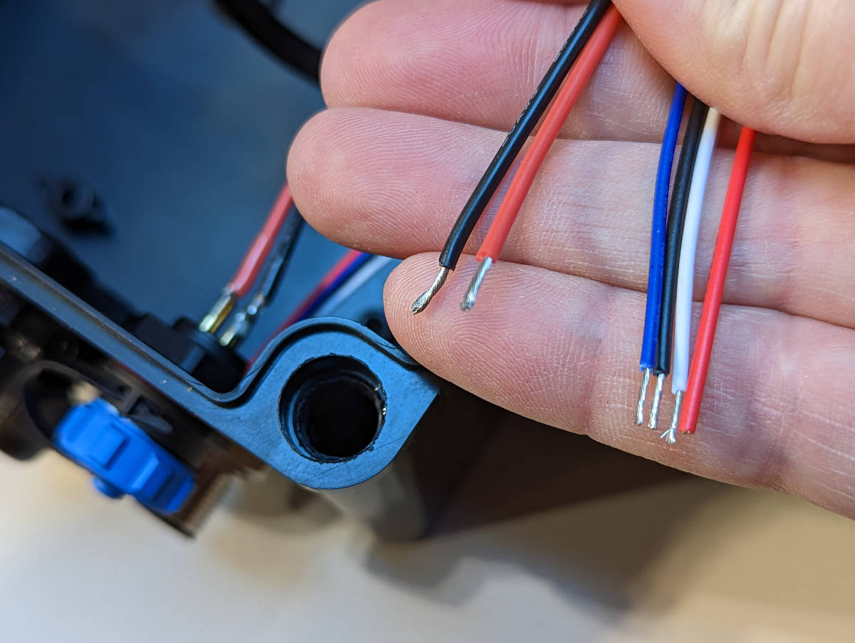
Stripped power and CAN wires.
The next step is to connect the wires to the PCB connectors. The power connector should be connected to the terminal plug as shown in the following figure.
When you plug in the terminal plug, be very careful to plug it to the input connector on the SH-RPi. You may damage all devices on the stack if you plug it to the 5V output connector!
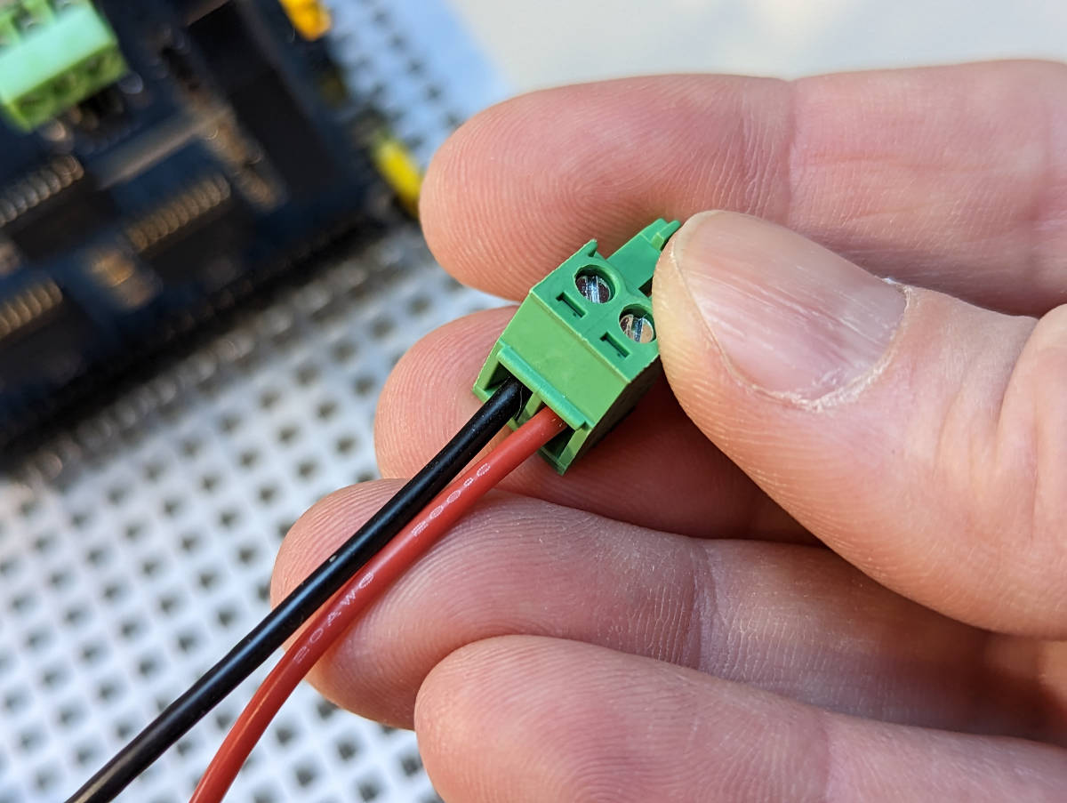
Power connector terminal plug arrangement.
Then, the CAN wires should be connected to the CAN HAT connector CAN0 as shown below. Black is ground, white is CAN high (H) and blue is CAN low (L).
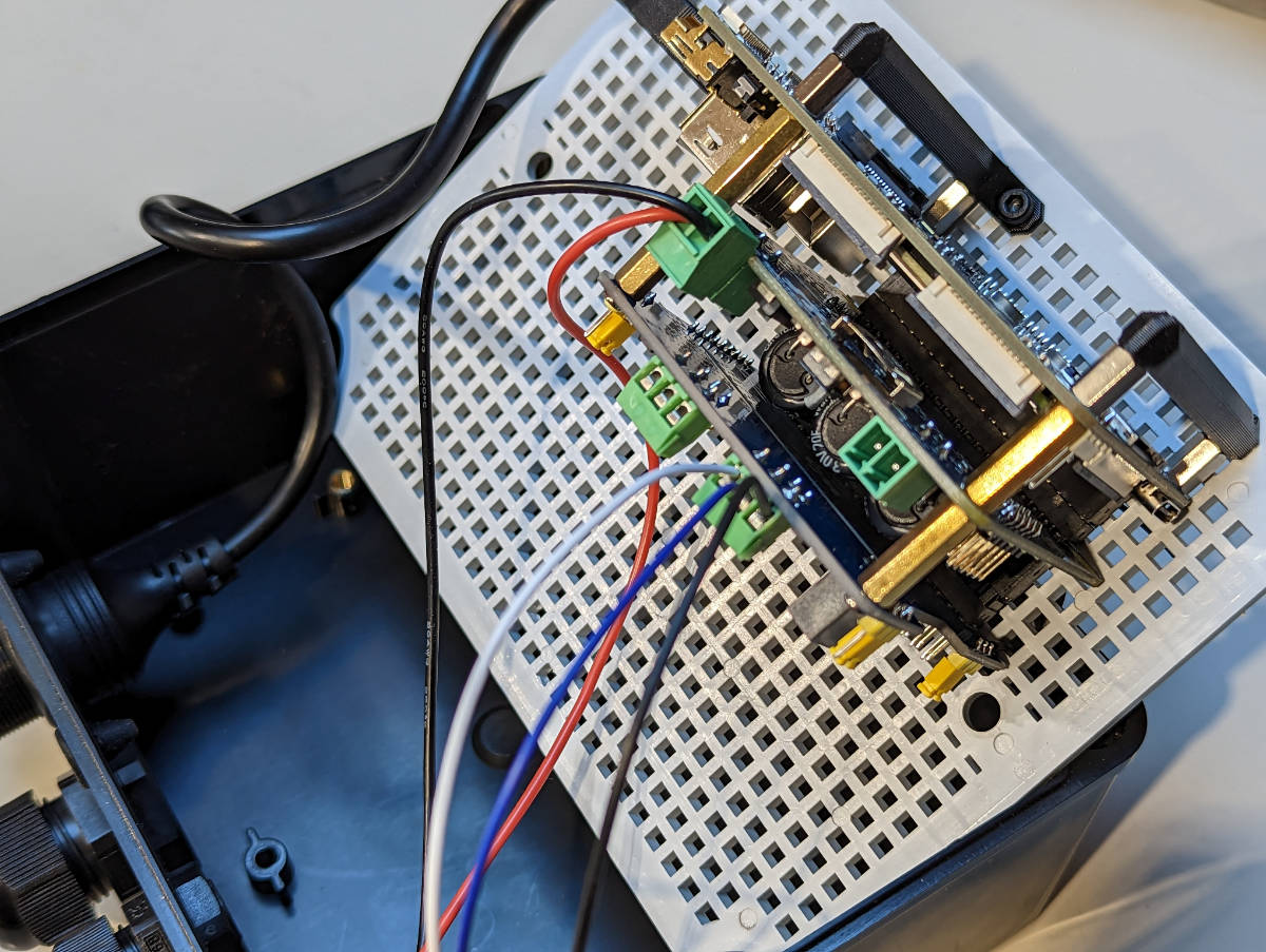
Final wiring arrangement.
Powering from NMEA 2000
When using on a boat, you can also power the system from the NMEA 2000 network. In this case, all wires from the NMEA 2000 connector are used.

When powering the device from the NMEA 2000 network, all wires from the NMEA 2000 connector are used.
The black and red wires are connected to the power terminal plug, with a short piece of black wire spliced to GND terminal as shown in the following figure. The short black wire connects to the GND terminal of the CAN HAT CAN0 connector.
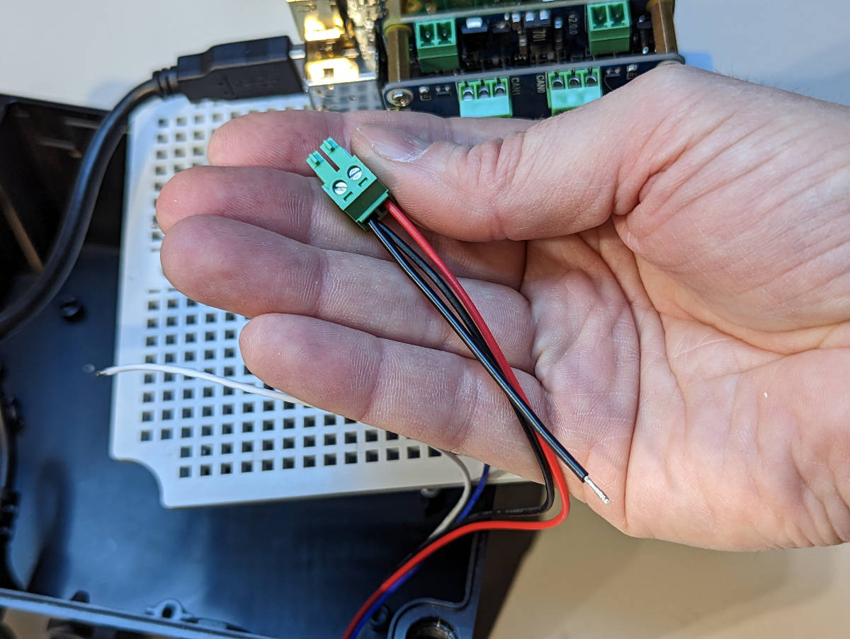
Connect the NMEA 2000 GND wire to both the power terminal plug and the CAN HAT CAN0 connector.
The next figure shows the final wiring arrangement when powering the device from the NMEA 2000 network.
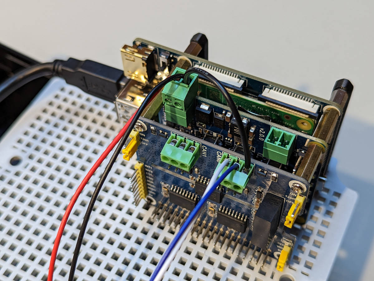
Final wiring arrangement when powering the device from the NMEA 2000 network.
Securing the Stack
Finally, the loose end of the stack can be secured to the base plate using small zip ties, but as an alternative, simple tie wraps are a simple and easy to use alternative. The following two figures show the tie wrap installation.
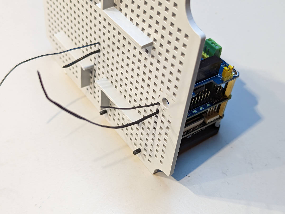
Tie wraps inserted.
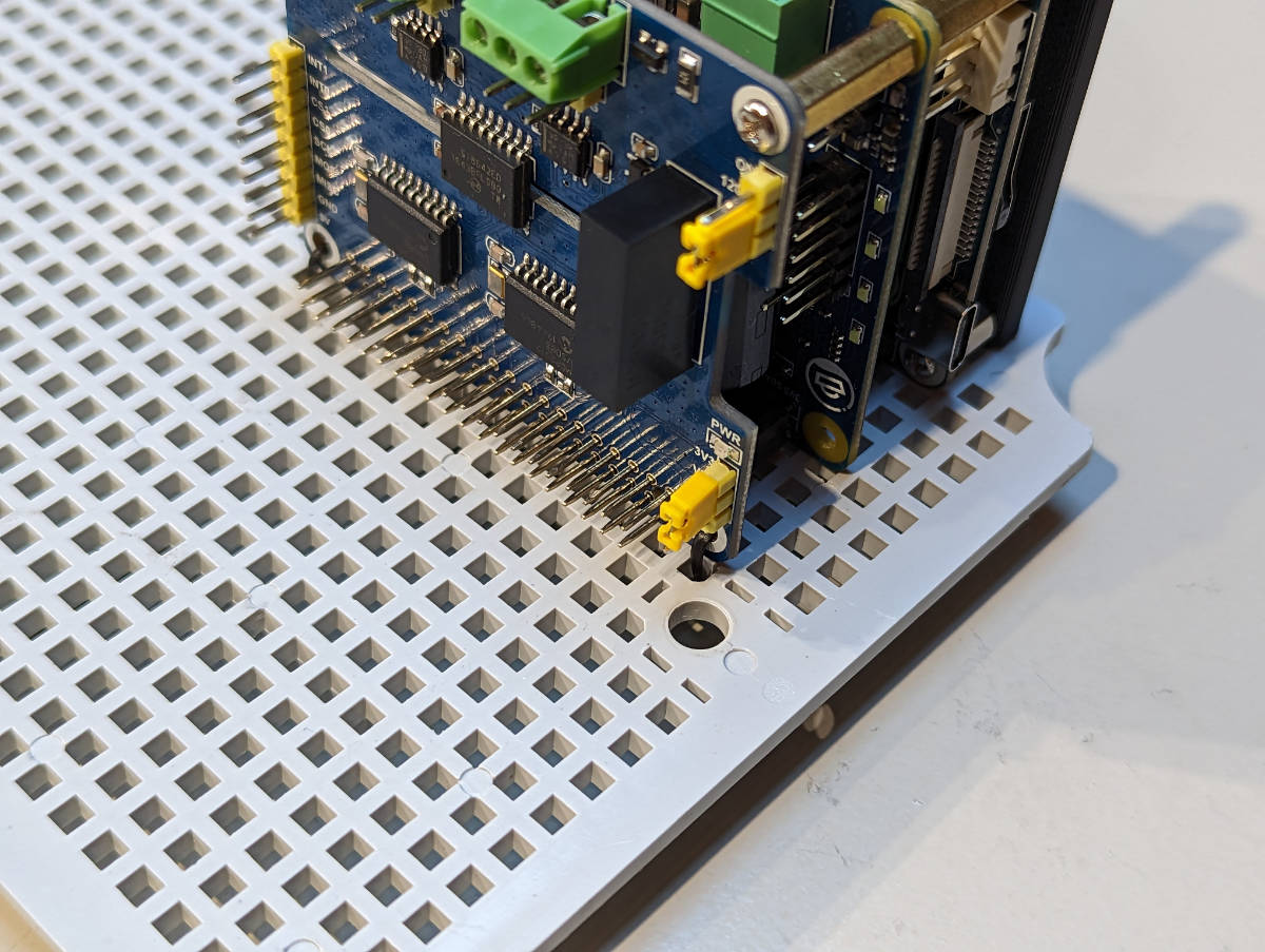
Finished tie wrap installation.
Finishing the Assembly
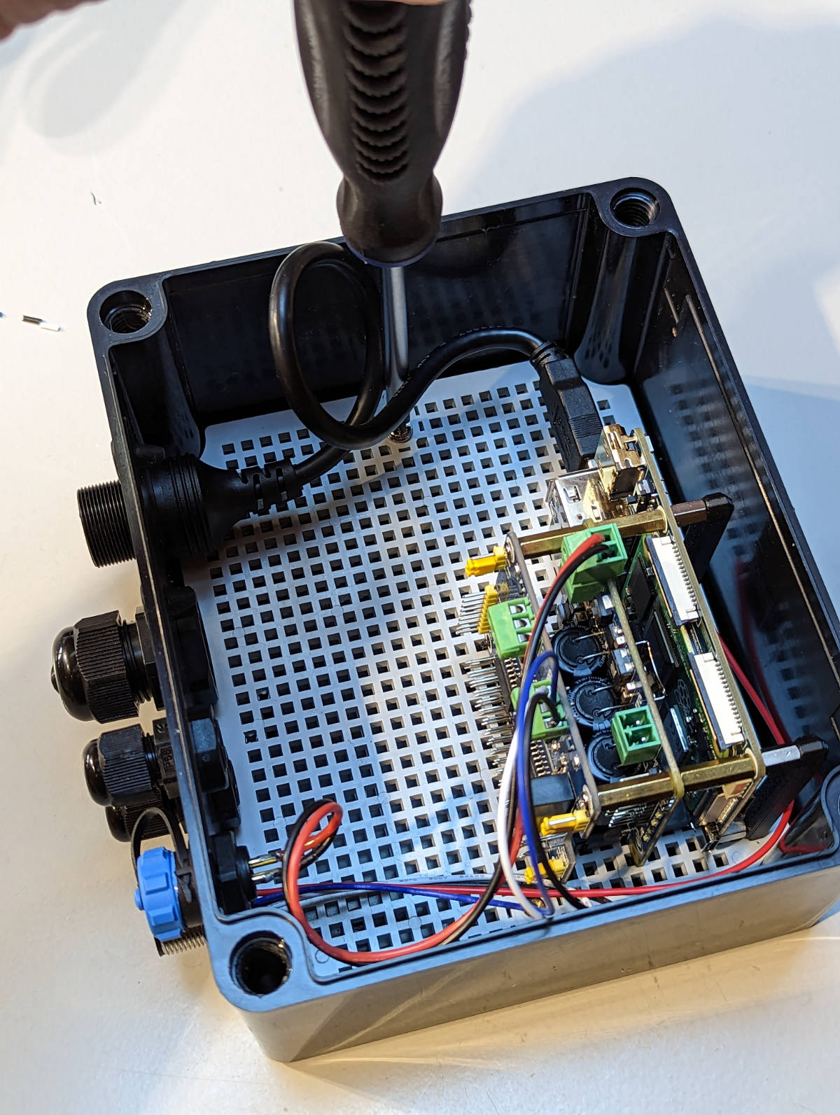
At this point, the base plate can be inserted into the enclosure.
Base plate in place.
Secure the base plate to the enclosure with the provided screws.
Screwing the base plate to the enclosure.
Finally, the assembly is done. The figure below shows the setup happily blinking away in the enclosure.
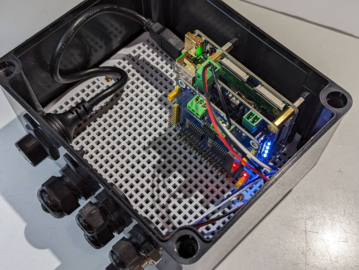
The finished setup.
The enclosure can be mounted to a wall or a bulkhead through the corner holes shown in the figure below.
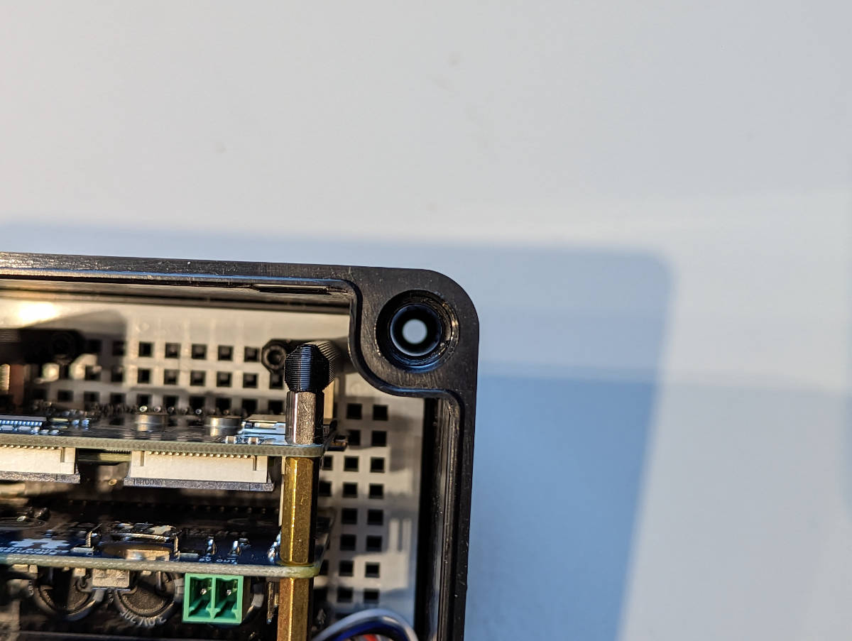
Mounting hole locations.
Drilling Holes
If you’re using an enclosure without pre-drilled holes, you’ll need to drill the holes yourself.
At a minimum, you need one hole for power input and, for any metal enclosure, another for a Wi-Fi antenna or a wired Ethernet connector.
Plan the hole/connector placement to fit your intended installation location. If you’re planning to wall-mount the enclosure, place the connectors facing down to minimize the chances for water ingress.
Both aluminum and polycarbonate are relatively soft and can be drilled with a step drill bit (one that looks like a small metal Christmas tree). When drilling plastic, standard metal drill bits may easily bite too hard and crack the wall.
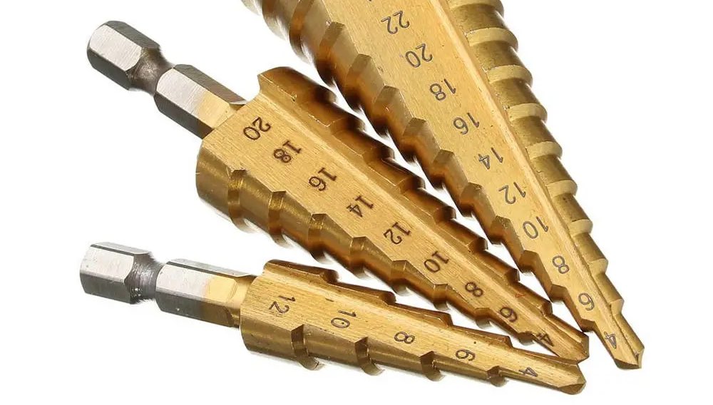
An example of step drill bits.
Suitable hole sizes for different connectors:
- SMA (Wi-Fi antenna): 6.5-7 mm or 1/4"
- PG7 cable gland and M12 (NMEA 2000) panel connector: 12.5 mm or 1/2"
- SP13 panel connectors (blue-black plastic connectors): 13 mm.
- PG9 cable gland: 16 mm or 5/8"
- RJ45 panel connector: 21-22 mm
- USB type A panel connector: 21-22 mm
Mounting the Raspberry Pi
The enclosures provided by Hat Labs include mounting adapters that can be used to mount the Raspberry Pi.
Soldering the Panel Connectors
When soldering the internal wires to the panel connectors, always use heat shrink tubing on the individual wires. Always remember to slide the heat shrink onto the wires before soldering… Usually, you can first add solder to the connector pin cavity and then re-melt the solder and insert the wire.
Connecting a Fan
Placing a fan inside the enclosure is recommended to improve air circulation and heat transfer through the enclosure surfaces. A small 40mm fan can be mounted in the enclosure with double-sided tape or hot glue.
The fan should be connected to the generic 5V output connector on the SH-RPi:
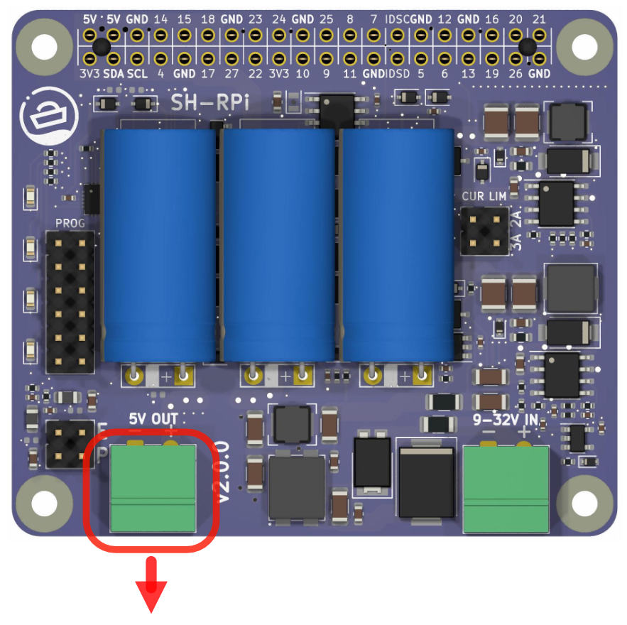
Connect the fan to the connector indicated by the red arrow.
Finalizing Installation
Once you have completed drilling holes, mounting the Raspberry Pi, soldering the panel connectors, and connecting the fan, close the enclosure to protect your SH-RPi and Raspberry Pi from the elements. Ensure that all connections are secure and the enclosure is tightly sealed to prevent water ingress.
Testing the System
After completing the installation, power up your Raspberry Pi and SH-RPi system to ensure that everything is functioning correctly. Check that the Raspberry Pi boots up, the fan is operating, and the SH-RPi is communicating with the Raspberry Pi. Once you have verified that everything is working, you can proceed with configuring your software and integrating the system into your intended environment.
Congratulations! You have successfully completed the hardware assembly and enclosure setup for your SH-RPi and Raspberry Pi system.