Hardeware Description
Tour Around the Board
Different functional blocks of the Sailor Hat for Raspberry Pi are described below.
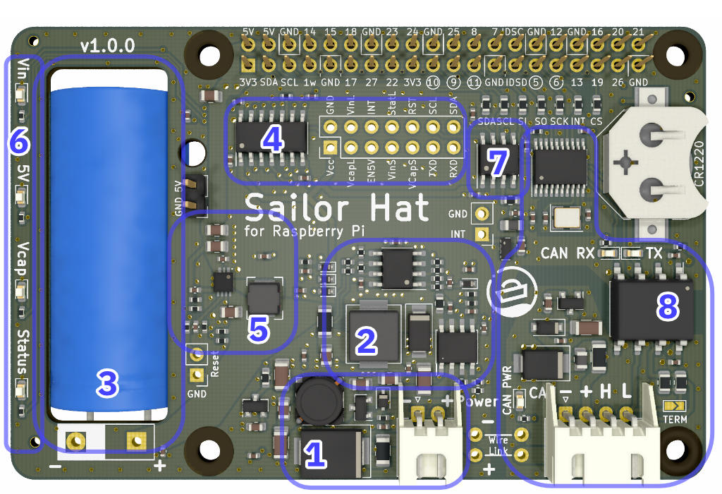
Functional blocks of the SH-RPi.
- Power input and protection.
Power input is provided through a 2-pin JST XH connector.
The permitted voltage range is 8-32V.
The protection circuitry at power input includes:
- 2.5A SMD fuse
- 33V transient voltage suppressor (5000W peak pulse power capability)
- Pre-filter for conducted electromagnetic interference
- Reverse polarity protection
- Step-down (buck) converter with current limiting. The buck converter transforms the input voltage into a 2.65V potential that the supercapacitor can handle. The step-down converter circuit also includes a separate current limiter that throttles the supercapacitor input current to cap the maximum device current draw to 0.8A (at 12V).
- A 60F 2.7V supercapacitor. The supercapacitor acts as a power reservoir for the Raspberry Pi. It can power a Raspberry Pi 4B for up to 80 seconds (subject to the amount of additional peripherals, of course), and lower-power models for much longer. The supercapacitor also makes it possible to power the Raspberry Pi using a low-power interface such as the NMEA 2000 bus that limits an individual node current to 1.0A, including high-speed transients.
- Microcontroller.
The SH-RPi operations are controlled by an ATtiny1614 microcontroller.
The microcontroller performs the following functions:
- Measures the input voltage
- Measures the supercapacitor voltage
- Controls the Vin, Vcap, and Status leds
- Controls the boost converter output
- Receives real-time clock interrupt information (can be used as an external interrupt source as well)
- Communicates the SH-RPi status to the Raspberry Pi service over I2C
- Step-up (boost) converter. The boost converter converts the 0.5-2.65V potential stored in the supercapacitor into the 5V Raspberry Pi input voltage. The boost converter operation is controlled by the microcontroller. The microcontroller enables the boost converter when the supercapacitor voltage has risen above 1.8V. During system shutdown or watchdog reboot, the microcontroller disables the boost converter to cut the Raspberry Pi input voltage.
- Status LEDs. The status LEDs indicate the board operational status LEDs as described in Section LEDs.
- Real-time clock (optional). The board includes an optional DS3231MZ real-time clock that can keep accurate time even in the absence of internet or GPS connectivity. The RTC communicates with the Raspberry Pi over I2C.
- CAN bus (NMEA 2000) interface. The SH-RPi includes an MCP2515 CAN controller and an ISO1050DUB CAN transceiver that provide an isolated, NMEA 2000 compliant CAN bus interface. The interface can be used as a generic CAN interface if external power is provided to the CAN connector.
Connectors

SH-RPi connectors.
- Power connector. The power connector is a JST XH compatible header. The Hat Labs sales kit includes a compatible pigtail cable.
- CAN bus (NMEA 2000) connector. NMEA 2000 or other CAN bus can be connected to this connector.
- Wire link. Main power input and CAN section power input pins can be connected together by soldering a wire to the wire link headers. The main use case is to power the Raspberry Pi using a single NMEA 2000 cable without having to splice any wires.
- Stackable Raspberry Pi GPIO header. This is a standard 2x20 pin Raspberry Pi GPIO header. Additional hats can be placed on top of the Sailor Hat for Raspberry Pi as long as there are no conflicting pins or I2C addresses.
- 5V output. The 5V output header can be used to power a fan or other peripherals requiring a 5V input.
- ATtiny1614 breakout header. The pins of the onboard ATtiny1614 microcontroller are broken out to this header. The header can be used to program the microcontroller or to implement new functionality.
- Reset header. The reset header can be used to forcibly hardware reset the Raspberry Pi. The header is connected to the boost converter Enable pin. Pulling the Reset pin low turns the boost converter off. When the Reset pin is connected to 3.3V, it forces the boost converter to stay on regardless of the microcontroller state. This can come handy for example when programming the microcontroller using the Raspberry Pi itself: you don’t want the Raspberry Pi to shut down during the programming.
- ATtiny interrupt header. This header is connected to the microcontroller INTerrupt pin. This pin can be used in the future by the optional RTC or an external interrupt source to wake up the Raspberry Pi.
- CR1220 battery connector for real-time clock. The optional real-time clock requires a CR1220 backup battery to keep time when the system is powered off. The battery must be oriented positive (flatter) side up.
Power Supply
The SH-RPi includes an integrated power supply subsystem that provides a clean power supply to the Raspberry Pi from a noisy power source, like a boat’s “house” battery system. The power supply permits input voltages between 8-32 V (although the output will be disabled if the input is less than 10V, to protect the vessel batteries from deep discharging).
The input current is limited to a maximum of 0.8 A at 12 V. Above that limit, a current limiting circuit starts throttling the buck converter to control the maximum current drawn from the power input.
The power supply output voltage is normally at 5.1 V. The maximum steady-state output current is about 1.2 A, or about twice the current consumption of a Raspberry Pi 4B. Maximum output currents over 3 A can be sustained over several hundred milliseconds.
Peripherals
LEDs

SH-RPi indicator LEDs.
SH-RPi includes a number of LEDs to indicate the state of operation.
- Main LED array
- CAN power (on whenever input voltage is present at the CAN power pins)
- CAN receive and transmit (blink whenever data is received or transmitted over the CAN bus)
The main LED array LEDs are as follows:
- Vin: A green LED that indicates the 12/24V input voltage. The LED states are:
- Vin < 10 V: LED off
- 10 V < Vin < 11.5 V: LED blinking 50% on/off
- Vin > 11.5 V: LED solid on
- 5V: Red LED solid on when 5V is enabled by the microcontroller
- Vcap: Green LED that blinks according to the supercapacitor voltage. 100% off is 0 V, 100% on is 2.75 V.
- Status: Different blink patterns indicate the state of the board as follows.
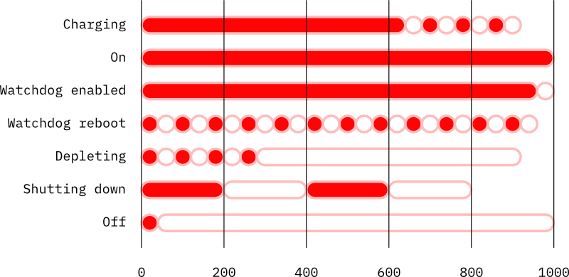

Different board statuses are:
- Charging: the supercapacitor is charging but the voltage is too low to turn the 5V output on
- On: 5V output is turned on
- Watchdog enabled: 5V output is on, watchdog is enabled
- Watchdog reboot: The daemon has not communicated in 10 seconds; the Raspberry Pi is reset by turning 5V off for two seconds
- Depleting: Input voltage is not present and the supercapacitor is depleting
- Shutting down: The daemon has requested a shutdown; the watchdog is turned off and the firmware waits until the kernel is shut down (as indicated by SDA being set low)
- Off: 5V is turned off and the board is expected to be powered off. If the board remains powered, it will restart in 5 seconds.
CAN Bus (NMEA 2000)
NMEA 2000 is a ubiquitous communications standard used for connecting sensor, control, and display devices on boats and ships. It is based on the Controller Area Network (CAN bus) which is a vehicle bus standard designed to allow devices to communicate with each other without a host computer.
SH-RPi features an isolated CAN interface that allows safe and NMEA 2000 compliant interconnection of devices.
The CAN interface is implemented with an MCP2515 controller and an ISO1050DUB isolated transceiver.
The Raspberry Pi communicates with the MCP2515 over an SPI interface. SH-RPi uses by default Raspberry Pi SPI0 with GPIO6 as a custom Chip Enable (CE) pin. This is done to allow simultaneous operation with other devices reserving the standard SPI pins. The interrupt pin is GPIO5.
I2C
I2C (Inter-Integrated Circuit) is a popular synchronous serial communication bus commonly used for interfacing with a number of different ICs. It uses two data wires in addition to voltage and ground.
The SH-RPi microcontroller communicates with the Raspberry Pi operating system over I2C. The microcontroller uses I2C address 0x6d.
If the optional DS3231 real-time clock is installed, it additionally reserves the I2C address 0x68.
Remapping Peripherals
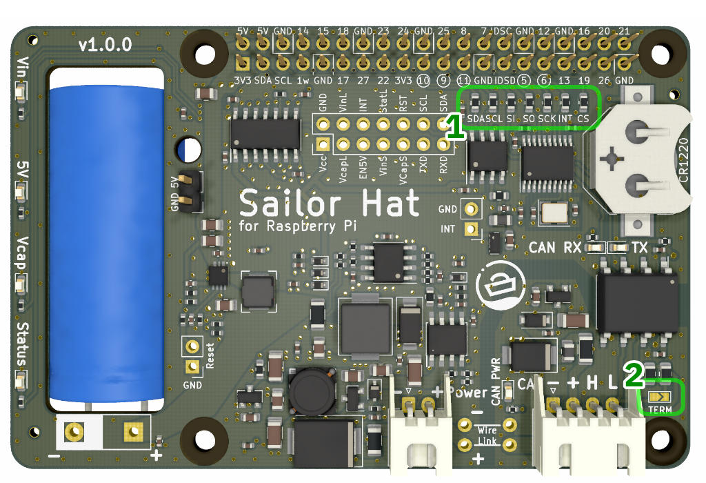
SH-RPi hardware jumpers.
For advanced use, all GPIO pins used by the Sailor Hat for Raspberry Pi can be disabled or remapped using the hardware jumpers. The hardware jumpers are 0603 size 0 ohm resistors that can be unsoldered from the board. Thin wires can then be soldered to the resistor pads for routing the peripherals to desired GPIO pins.