NMEA 2000
Introduction
NMEA 2000 is a networking standard for marine electronics, used by most modern marine electronics hardware.
It is is constructed from a a number of devices connected to a single bus, called the network backbone.
All devices on the network can both transmit and receive messages.
An illustration of a typical NMEA 2000 network with some example devices is shown below.

Example NMEA 2000 Network.
Figure components are:
- 1
- N2K power cable. Every NMEA 2000 network segment must be connected to boat's 12 V power system. Ideally, the power connection should be roughly in the middle of the backbone.
- 2
- Network male and female terminators.
The network backbone must be terminated with exactly two 120 ohm resistors for proper network operation. The are mandatory and essential!
- 3
- Drop cables are connected to the backbone using T-connectors.
The T-connectiors can have one or multiple drop cable connections.
- 4
- Backbone cables extend the backbone. The maximum length of the network, measured from terminator to terminator,
should not exceed 100 m.
- 5
- Drop cables connect individual devices to the backbone.
The maximum length of the drop cable is 6 m.
- A
- A display device such as a Multi-function Display (MFD).
- B
- A wind sensor.
- C
- A temperature sensor.
- D
- An SH-wg device.
The network backbone is shown in pale blue color.
All devices connect to the backbone using drop cables.
Only one device can be connected to a single drop cable.
At the very minimum, the network must have a 5-way T-connector, two terminators, a power connection, and two devices with their own drop cables.
1 - NMEA 2000 Power Feed
This page describes how to power the NMEA 2000 network.
Connecting the Network Power Feed, Theory
The NMEA 2000 network supplies power to devices connected to it.
Even though some devices are externally powered, power connection is a mandatory part of the network. No data can be transmitted without it.
The voltage of the network is 12 V DC. If your boat has a 24V nominal electrical system, you must use a 24V to 12V DC converter to power the network.
The maximum current draw of the network is 3 A.
The network must be fused with a 3 A fuse to protect the network wiring.
The NMEA 2000 network should always be connected using a switch. Without a switch, the network is always powered on and the devices will deplete the boat battery.
Finally, the NMEA 2000 shield, or the braided sheath coveering the inner cable pairs, must be connected to the boat’s ground at the power connection point. This is important for proper network operation because it prevents electrical noise from alternators, starter motors, inverters and other high current devices from interfering with the network.
A schematic of the network power connection is shown below.

NMEA 2000 Power Connection
Connecting the Network Power Feed, Practice
Step by step instructions for connecting the network power feed are shown below.
First, cut the power cable to length. The cable should be long enough to reach the power connection point from the network backbone T-connector. Leave some slack, though – nothing is more annoying than a cable that is too short!
Cutting the cable to length
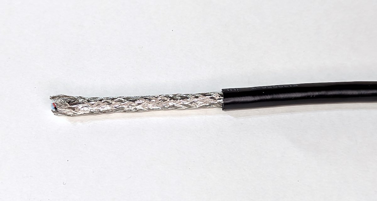
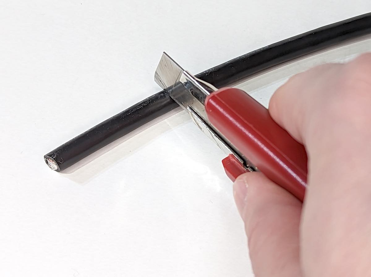
Strip the outer sheath of the NMEA 2000 power cable.
Required length depends on the location of the power connection point.
If the 12V and ground connections are close to each other, the cable can be cut to as short as 5 cm (2 in), but if the 12V and GND connection poits are separated, make the wires accordingly longer.
You can use sharp knife or a dedicated wire stripper, but be careful not to cut the shield braiding. You can use the off-cut from the previous step to practice and perfect your skills.
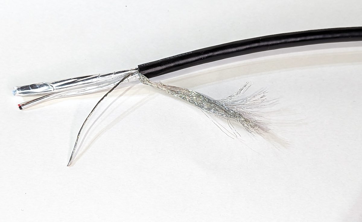
Undo the shield braiding and cut it away. You’ll find a twisted bare shield wire as well. Do not cut it, it’ll be used later.
Strip the foil shield from the wires.
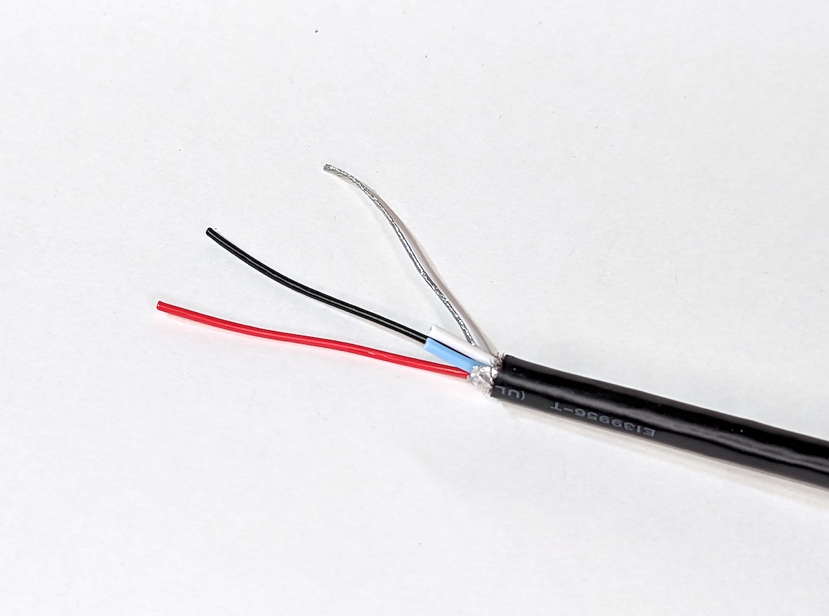
Cut the blue and white signal wires away. The signal wires are not used in the power connection. Leave short stubs of the signal wires to prevent them from shorting to the shield strands.
Slide a bit of larger diameter heat shrink tube on top of the whole cable. Then, cover the signal wire stubs with a bit of smaller diameter heat shrink tube. Also cover the bare shield wire with a bit of heat shrink tube. In the photo below, the signal wires are covered with yellow tube and the shield wire is covered with transparent tubing.
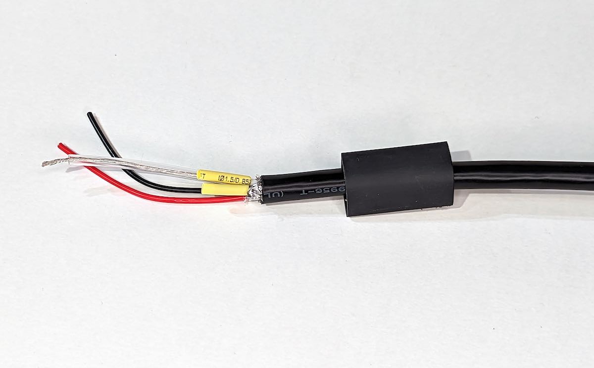
Heat shrink tubes in place
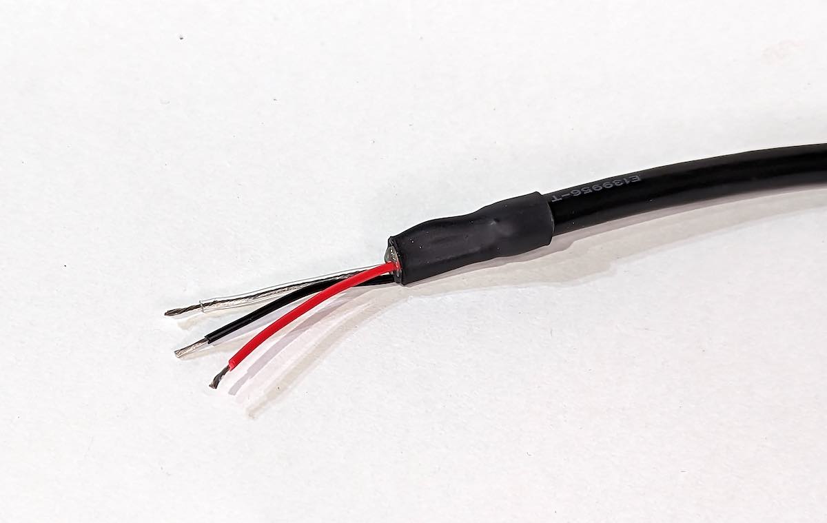
Apply heat to shrink the heat shrink tubes, first to the smaller diameter ones, then to the larger one. In the photo below, the larger diameter heat shrink tube has some hot glue coating. That results in a thicker but more or less waterproof protection.
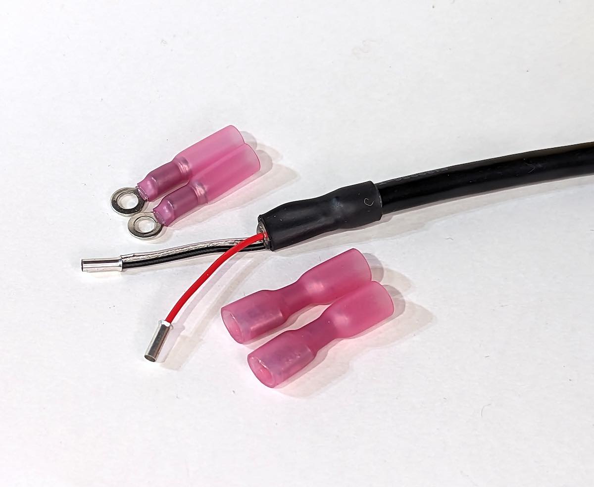
Strip the red and black wire insulation. The length depends on the type of terminals, but about 6 mm (1/4 in) is usually adequate.
Crimp suitable terminals to the wires: one terminal to the red wire and one for both the black wire and the shield.
Depending on your electrical panel, you can use wire end ferrules or small ring or spade terminals, as shown in the photo below.
Connect the black wire and the shield to the ground terminal in the electrical panel. Connect the red wire to the 12V terminal. The 12 V circuit must be fused with a 3 A fuse or a circuit breaker.
If you don’t have an electrical panel on your boat, you can install an inline fuse holder and a separate switch to the red wire. In that case, you can use butt connectors or solder the wires together.
Finally, connect the network connector to a T-connector on the network backbone, and you are done!
2 - Powering Devices through the NMEA 2000 Network
It is possible to power your custom devices via the NMEA 2000 network. To stay compliant with the NMEA 2000 specification and to ensure safe and uninterrupted operation of the NMEA 2000 network, it is important to observe some restrictions in the device connections.
Galvanic isolation, or just isolation in short, is at a central role here.
Isolation is a technique to prevent the flow of electric current between two circuits.
At heart, it means that the two circuits do not share electrical ground.
This can be tested by measuring contiuity between the two circuit ground wires.
If there is no continuity, the circuits are isolated from each other.
The following diagrams illustrate the valid powering schemes.
In the diagrams, dashed lines illustrate the isolation barrier.
Note that even though the figures and captions refer to the SH-RPi, the same rules apply to all other devices such as the SH-ESP32.
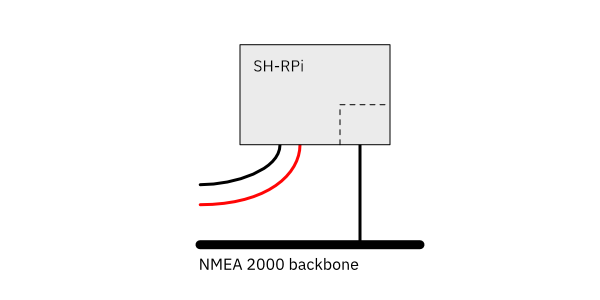
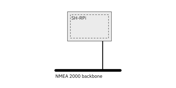
Always OK: SH-RPi powered with a dedicated power cable.
OK: SH-RPi powered via the NMEA 2000 network, no external connections.
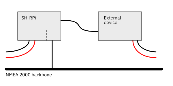
OK: SH-RPi powered with a dedicated power cable and connected to external devices with a galvanic connection such as USB or unisolated RS-422.
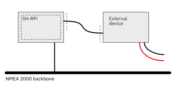
OK: SH-RPi powered via the NMEA 2000 network and connected to external devices with an isolated connection such as Ethernet or isolated NMEA 0183.
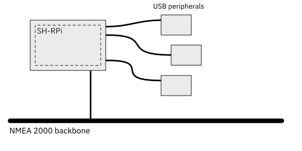
OK: SH-RPi powered via the NMEA 2000 network having peripherals such as keyboard, mouse, or a GPS receiver that are powered by the Raspberry Pi and not connected elsewhere.
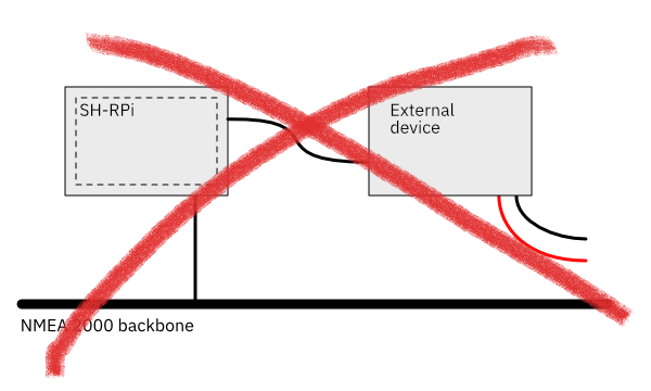
Not permitted: SH-RPi powered via the NMEA 2000 and connected to external devices with a galvanic connection. This setup will cause a lot of noise and may impact the reliability of the Raspberry Pi or other devices.