HALSER User Guide
| Description | User guide for HALSER, an ESP32-C3 serial interface board for marine applications |
| Author(s) | Hat Labs |
| Repository | https://github.com/hatlabs/halser |
Introduction
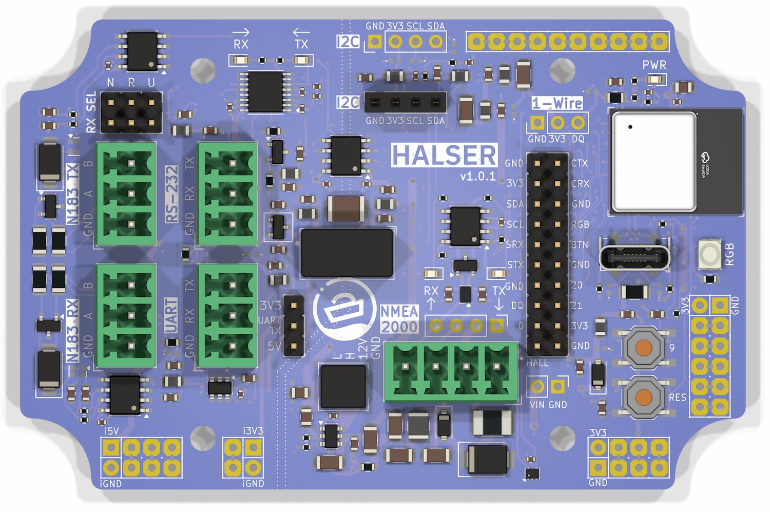
HALSER is an ESP32-C3 based development board designed for marine serial interface applications. It bridges legacy serial devices — NMEA 0183 instruments, RS-232 equipment, and UART peripherals — to NMEA 2000 networks and WiFi.
Shop Link
Purchase HALSER from the Hat Labs web shop.
Key Features
- ESP32-C3 microcontroller — 32-bit RISC-V core, 4 MB flash, WiFi
- Wide-range power input — 5–32 V with surge and reverse polarity protection
- NMEA 2000 — CAN bus interface via 4-pin pluggable terminal block
- RS-485 TX and RX — Bidirectional NMEA 0183 communication
- RS-232 — Legacy serial device support
- UART — General-purpose serial (3.3 V / 5 V selectable via jumper)
- 1-Wire and I2C — Expansion buses for temperature sensors and other peripherals
- USB-C — Programming and serial communication
- RGB status LED — Visual indication of board state
- EMC-compliant design — Won't interfere with navigation or radio equipment
- Compact form factor — Fits standard 100×68×50 mm waterproof enclosures
What's in the Box
- HALSER board
- 4-pin pluggable screw terminal (NMEA 2000 and power)
- Two 3-pin pluggable screw terminals (serial I/O)
- Two jumper headers (serial configuration)
Where to Start
- New to HALSER? Start with the Getting Started guide for hardware setup.
- Connecting devices? See the Usage section for wiring and interface details.
- Building firmware? The Software section covers development options.
- Looking for specs? The Hardware Description has detailed technical reference.
Getting Started
Getting Started
This section walks you through the initial setup of your HALSER board.
What You Need
- HALSER board
- Power source: NMEA 2000 network or any 5–32 V DC supply
- Panel connectors or cable glands for NMEA 2000, power, and any serial interfaces you plan to use (see Enclosures)
- A waterproof enclosure (see Enclosures)
- USB-C cable for programming
- Development environment (see Software)
Quick Start
-
Wire power and NMEA 2000 — Connect your power source to the 4-pin terminal block. See Connecting Power and NMEA 2000 for wiring details.
-
Verify power — The red power LED indicates that the board has power. If firmware is running, the RGB LED also lights up — with the default firmware it shows a rainbow animation, confirming the ESP32-C3 is operating correctly.
-
Set up your development environment — HALSER is a development board. For most use cases, you will need to build and flash custom firmware. See Software Overview for options.
-
Connect your serial device — Wire your NMEA 0183, RS-232, or UART device to the appropriate terminal block. See the Usage section for interface-specific wiring guides.
-
Flash and test — Upload your firmware via USB-C and verify that data flows between your serial device and the NMEA 2000 network or WiFi.
Default Firmware
HALSER ships with a basic NMEA 0183 → NMEA 2000 gateway firmware for quick evaluation. See Default Firmware for details. For most practical applications, you will want to develop custom firmware tailored to your specific needs.
Connecting Power and NMEA 2000
HALSER is powered through the 4-pin NMEA 2000 terminal block. The same connector provides both power and CAN bus connectivity.
Powering via NMEA 2000
If you are connecting HALSER to an NMEA 2000 network, connect the NMEA 2000 cable to the pluggable terminal block as follows:
| Pin | Signal | NMEA 2000 Color |
|---|---|---|
| 1 | GND | Black |
| 2 | Vin | Red |
| 3 | CAN H | White |
| 4 | CAN L | Blue |
The NMEA 2000 bus voltage is nominally 12 V. HALSER's power input accepts 5–32 V, so it works directly on the bus.
NMEA 2000 Shield
Per the NMEA 2000 standard, the cable shield (bare/drain wire) must be left unconnected at device ends. Only connect the shield at the designated grounding point on the NMEA 2000 backbone.
Powering Without NMEA 2000
If you only need power (no CAN bus), connect your DC supply to pins 1 (GND) and 2 (Vin) only. Any 5–32 V DC source is suitable.
Verifying Power
When power is applied, the red power LED lights up, indicating that the 3.3 V rail is active. If firmware is running on the ESP32-C3, the RGB LED also turns on — with the default firmware it shows a rainbow color cycle, confirming the microcontroller is operating correctly.
Enclosures and Panel Connectors
For use on a boat, HALSER should always be placed in a waterproof enclosure. The board is designed to fit standard 100×68×50 mm waterproof enclosures.
Recommended Enclosure
The easiest way to get started is the Hat Labs pre-drilled enclosure. It comes with 5 pre-drilled 13 mm holes and 3 PG7 blind plugs — no drilling required. The holes accept NMEA 2000 panel connectors, SP13 connectors, and PG7 cable glands directly.
The enclosure is IP65-rated ABS with stainless steel (A4/AISI 316) screws and integrated wall-mount flanges.
Using a Generic Enclosure
Any 100×68×50 mm waterproof enclosure will fit HALSER. If your enclosure does not have pre-drilled holes, you will need to drill them yourself.
When drilling holes, always use a conical or step drill bit (one that looks like a small metal Christmas tree). Standard metal drill bits may easily bite too hard and crack the enclosure wall.
When planning connector placement, leave sufficient room for tightening the connector nuts and for the connector body. If you are wall-mounting the enclosure, place the connectors facing down to minimize the risk of water ingress.
Hole Sizes
| Connector Type | Hole Size |
|---|---|
| PG7 cable gland | 12.5 mm (1/2") |
| M12 (NMEA 2000) panel connector | 12.5 mm (1/2") |
| SP13 panel connector | 13 mm |
| PG9 cable gland | 16 mm (5/8") |
Grommets
Rubber or silicone grommets allow for higher cable densities than panel connectors or cable glands. However, they are less waterproof and require permanent cable attachment, making servicing more difficult.
Soldering Panel Connectors
When soldering internal wires to panel connectors:
- Always use heat shrink tubing on the individual wires
- Slide the heat shrink onto the wires before soldering
- Add solder to the connector pin cavity first, then re-melt and insert the wire
Usage
Serial Interfaces Overview
HALSER provides three physical serial interfaces:
- RS-485 — Differential signaling, standard for NMEA 0183
- RS-232 — Legacy serial voltage levels
- UART — Raw TTL-level serial (3.3 V or 5 V, selectable via jumper)
Each interface has its own terminal block connector on the board.
Transmit and Receive
Transmit: All three interfaces transmit simultaneously. The UART TX signal is converted to RS-485, RS-232, and TTL levels in parallel. In practice, you connect the transmit terminal block of whichever interface your receiving device expects.
Receive: Only one interface can receive at a time, selected by the RX SEL hardware jumper:
| Position | Active Receive Interface |
|---|---|
| N | NMEA 0183 (RS-485) |
| R | RS-232 |
| U | UART |
Place the jumper on the pin pair corresponding to the interface you want to receive on.
Note
RS-485 has separate TX and RX terminal blocks since it uses differential signaling with separate driver and receiver chips. RS-232 and UART each have TX and RX on a single 3-pin terminal block.
Using Different Bit Rates for RX and TX
Normally, the same bit rate is used for transmit and receive. However, since UART0 is available (USB CDC handles the console), custom firmware can assign UART0 to the TX pins and UART1 to the RX pins (or vice versa) via the ESP32-C3 GPIO matrix, allowing independent bit rates. For example, you could receive AIS at 38400 bit/s on RS-485 while transmitting NMEA 0183 at 4800 bit/s.
Interface Details
See the individual pages for wiring instructions and device-specific guidance:
NMEA 0183 (RS-485)
RS-485 is the standard electrical interface for NMEA 0183 communication in marine environments. HALSER provides separate RS-485 receive and transmit interfaces for bidirectional NMEA 0183 communication.
RS-485 RX — Receiving NMEA 0183 Data
The RS-485 RX interface is the primary input for receiving NMEA 0183 sentences from marine instruments.
Wiring
Connect the instrument's NMEA 0183 output to the RS-485 RX 3-pin terminal block:
| Pin | Signal | Description |
|---|---|---|
| 1 | GND | Signal ground |
| 2 | A | Non-inverting signal |
| 3 | B | Inverting signal |
A/B labeling
Typically, A is the non-inverting (+) signal and B is the inverting (−) signal. However, some devices and standards use the opposite convention. If communication doesn't work, try swapping A and B — reversing the polarity is safe and will not damage either device.
Bit Rate
The standard NMEA 0183 bit rate is 4800 bit/s. Some devices use higher rates:
| Bit Rate | Typical Devices |
|---|---|
| 4800 | Standard NMEA 0183 instruments (wind, depth, heading) |
| 38400 | AIS transponders, high-speed GPS receivers |
The bit rate is configured in firmware. The default firmware uses 4800 bit/s and provides a web UI setting to change it.
RS-485 TX — Sending NMEA 0183 Data
The RS-485 TX interface sends data to NMEA 0183 listeners such as chart plotters, autopilots, or displays.
Wiring
Connect the RS-485 TX 3-pin terminal block to the listener's NMEA 0183 input:
| Pin | Signal | Description |
|---|---|---|
| 1 | GND | Signal ground |
| 2 | A | Non-inverting signal |
| 3 | B | Inverting signal |
Compatible Devices
HALSER's RS-485 interfaces work with most NMEA 0183 instruments, including:
- Wind instruments (outputting MWV sentences)
- GPS receivers (outputting GGA, RMC, VTG)
- Depth sounders (outputting DPT, DBT)
- Heading sensors and compasses (outputting HDG, HDT)
- Speed sensors (outputting VHW)
- AIS transponders (outputting VDM, VDO — RS-422 is electrically compatible with RS-485)
RS-232 Devices
The RS-232 interface supports legacy serial devices that use RS-232 voltage levels (typically ±3–15 V). This is common on older marine equipment with DB-9 or DB-25 serial ports.
Wiring
Connect the device to the RS-232 3-pin terminal block:
| Pin | Signal | Description |
|---|---|---|
| 1 | GND | Signal ground |
| 2 | RX | Device transmit → HALSER receive |
| 3 | TX | HALSER transmit → device receive |
Signal Direction
TX and RX are labeled from HALSER's perspective. Connect HALSER's TX to the device's RX, and vice versa.
Signal Levels
RS-232 uses inverted logic with wider voltage swings than TTL:
- Logic high: −3 V to −15 V
- Logic low: +3 V to +15 V
- No hardware flow control (RTS/CTS) — only TX, RX, and GND are available
Compatible Devices
RS-232 is suitable for:
- Older chart plotters with serial ports
- Legacy marine instruments with DB-9 connectors
- Industrial serial devices
UART Devices
The UART interface provides TTL-level serial communication for devices that output raw UART signals. This is common on bare sensor modules, microcontroller boards, and some consumer devices.
Wiring
Connect the device to the UART 3-pin terminal block:
| Pin | Signal | Description |
|---|---|---|
| 1 | GND | Signal ground |
| 2 | RX | Device transmit → HALSER receive |
| 3 | TX | HALSER transmit → device receive |
Voltage Selection
The UART output voltage can be set to 3.3 V or 5 V using a jumper on the board.
- 3.3 V — For 3.3 V logic devices (most modern modules)
- 5 V — For 5 V logic devices (Arduino Uno, classic sensors)
The UART input is 5 V tolerant regardless of the jumper setting.
Compatible Devices
The UART interface is suitable for:
- Victron VE.Direct — Raw UART at 19200 bit/s. Connect the VE.Direct cable's TX, RX, and GND wires directly to the UART terminal block. Set the jumper to 3.3 V.
- Serial sensors — Sensors with UART I/O requiring galvanic isolation
- Microcontroller-to-microcontroller — Direct communication with Arduino, ESP32, or other MCU boards when isolation is required
Hardware
Hardware Description
ESP32-C3
HALSER is based on the ESP32-C3, a single-core 32-bit RISC-V microcontroller by Espressif. Key characteristics:
- CPU: 160 MHz RISC-V single-core processor
- Flash: 4 MB
- WiFi: 802.11 b/g/n (2.4 GHz)
- Bluetooth: Not available (ESP32-C3 supports BLE, but HALSER does not expose it)
- GPIO: 11 usable pins (see GPIO Reference below)
The ESP32-C3 is a popular choice for IoT applications due to its low cost, WiFi support, and compatibility with the Arduino and ESP-IDF ecosystems.
Board Functional Blocks
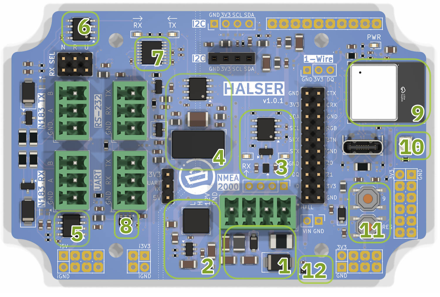
-
Power input and protection — 5–32 V input through the NMEA 2000 connector. Protection includes a 500 mA self-resetting fuse, reverse polarity protection diode, and overvoltage/ESD protection TVS diodes with two-stage noise filtering.
-
Switching power supply — Converts the wide input voltage range to the 3.3 V required by the ESP32-C3 and peripherals.
-
CAN transceiver — Provides the physical layer for NMEA 2000 communication. Connected to the ESP32-C3 TWAI (CAN) peripheral.
-
Isolation transformer and digital isolator — Galvanic isolation between the serial interfaces and the ESP32-C3, preventing ground loops and providing protection against voltage spikes.
-
RS-485 RX transceiver — Receives differential RS-485 signals (NMEA 0183 input).
-
RS-485 TX transceiver — Transmits differential RS-485 signals (NMEA 0183 output).
-
RS-232 transceiver — Level conversion for RS-232 serial communication.
-
UART level shifter — Voltage translation for the UART interface. Output voltage selectable between 3.3 V and 5 V via jumper.
-
ESP32-C3 module — The main microcontroller with integrated WiFi antenna.
-
RGB LED — SK6805 addressable LED for status indication.
-
Reset and user-defined push buttons — Reset button pulls the ESP32-C3 enable pin low. The user button (GPIO 9) is active low with an internal pull-up and can be used for any purpose in firmware.
-
Hall effect sensor — On-board hall sensor (GPIO 1) that can be activated with an external magnet through the enclosure wall, providing a button-like interface without compromising the waterproof seal.
Connectors
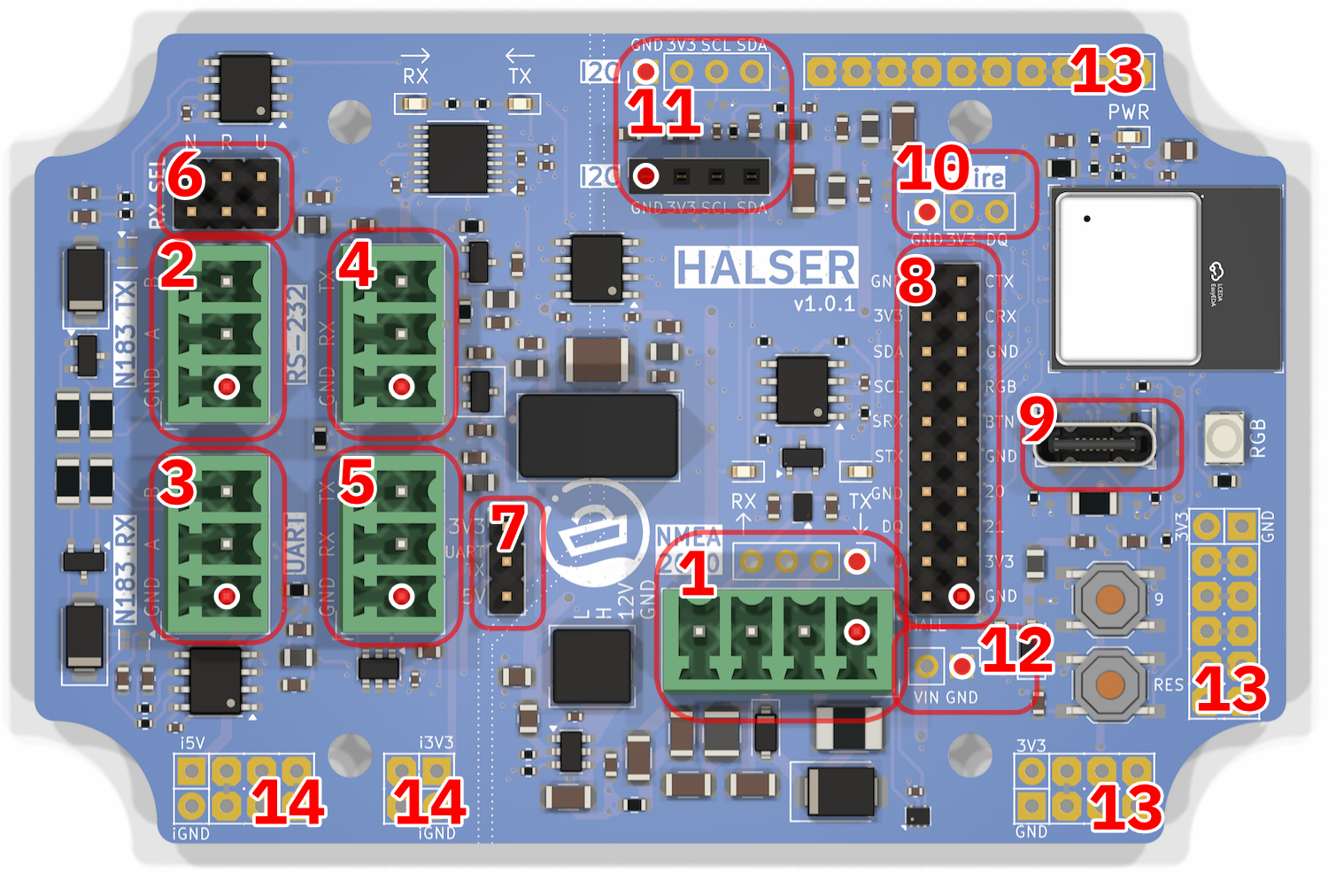
Identifying Pin 1
Pin 1 is marked on the diagram above with a red-white dot. On the physical board, each connector footprint has pin number labels and a corner marker on the silkscreen indicating Pin 1.
- NMEA 2000 — 4-pin pluggable terminal block (Phoenix MC 3.81 compatible). Power input and CAN bus.
- NMEA 0183 TX — 3-pin pluggable terminal block. RS-485 transmit.
- NMEA 0183 RX — 3-pin pluggable terminal block. RS-485 receive.
- RS-232 — 3-pin pluggable terminal block. Legacy serial interface.
- UART — 3-pin pluggable terminal block. TTL-level serial (3.3 V or 5 V).
- RX selection jumper — Selects the active receive interface (N = NMEA 0183 RS-485, R = RS-232, U = UART).
- UART voltage selection jumper — Sets UART output voltage to 3.3 V or 5 V.
- GPIO — 2.54 mm header breaking out available GPIO pins.
- USB-C — Programming and serial communication via USB CDC.
- 1-Wire — 3-pin 2.54 mm header (GND, 3V3, DQ). ESD-protected and RF-filtered.
- I2C (×2) — 4-pin 2.54 mm female header (GND, 3V3, SCL, SDA) and one unpopulated footprint for a second I2C connector.
- Vin — Protected and filtered input voltage connector, for reusing the input power for external devices.
- Proto pads — Unused pads for custom expansion.
- Proto pads (isolated) — Unused pads on the isolated board section for custom expansion.
GPIO Reference
| GPIO | Function | Notes |
|---|---|---|
| 0 | Available | |
| 1 | Hall effect sensor | On-board hall sensor |
| 2 | Serial TX | Default serial transmit. Can be remapped via GPIO matrix |
| 3 | Serial RX | Default serial receive. Can be remapped via GPIO matrix |
| 4 | CAN TX | NMEA 2000 transmit via TWAI peripheral |
| 5 | CAN RX | NMEA 2000 receive via TWAI peripheral |
| 6 | I2C SDA | I2C data line |
| 7 | I2C SCL | I2C clock line |
| 8 | RGB LED | SK6805 addressable LED data line |
| 9 | User button | User-programmable push button (active low with pull-up) |
| 10 | 1-Wire | 1-Wire data line (DQ) |
| 20 | Available | Directly available on the GPIO header |
| 21 | Available | Directly available on the GPIO header |
Pin Assignment Differences
HALSER's GPIO pin assignments differ from generic ESP32-C3 development kits. If you are adapting existing code, always verify pin assignments against this table.
Power Supply
- Input voltage: 5–32 V DC
- Input protection: Self-resetting fuse, reverse polarity diode, TVS diodes
- Regulation: Switching power supply (3.3 V output)
Galvanic Isolation
The serial interfaces (RS-485, RS-232, UART) are galvanically isolated from the ESP32-C3 and the NMEA 2000 bus. The isolation barrier runs across the board as shown below, separating the isolated serial section (left) from the non-isolated microcontroller section (right).
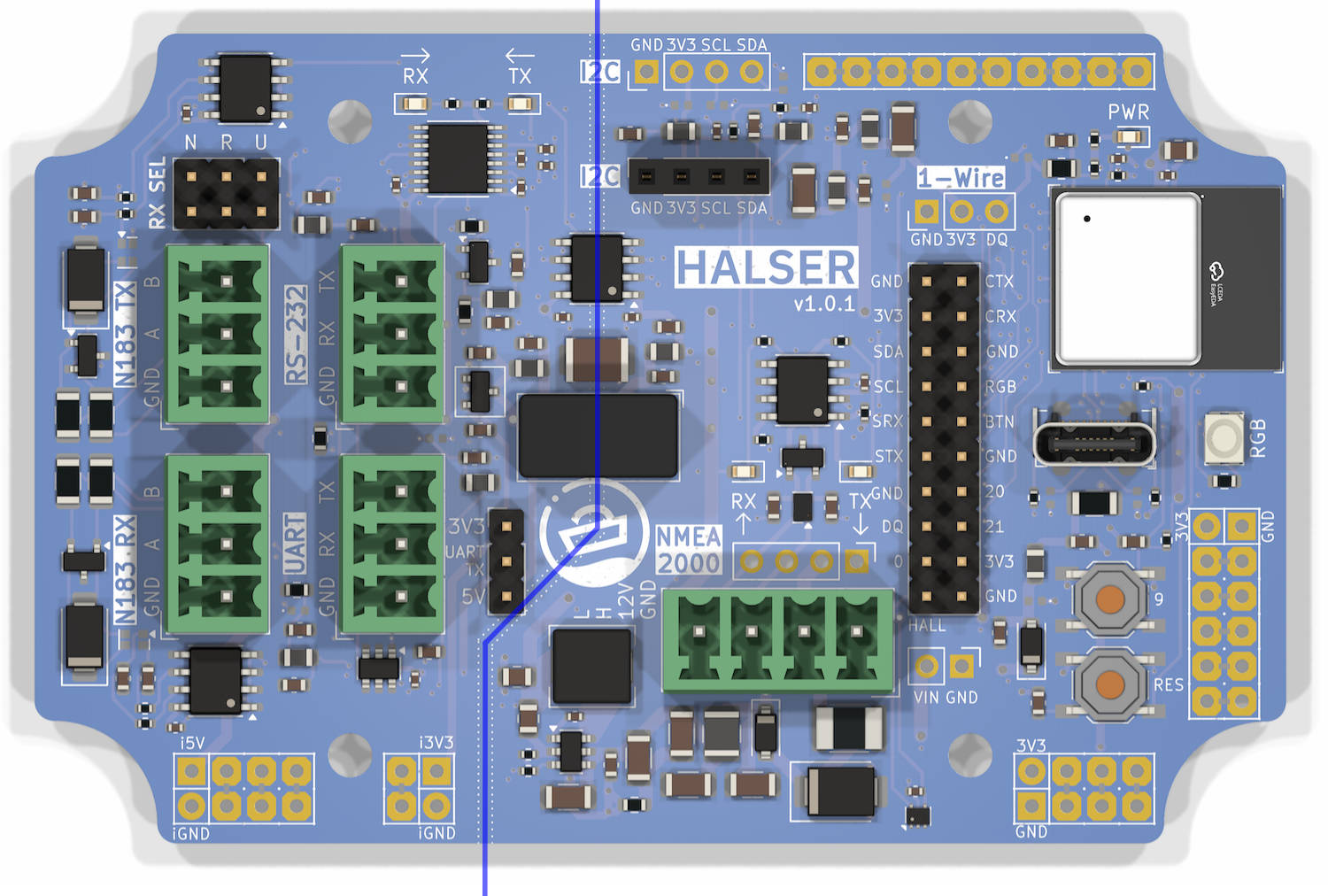
The isolation is implemented using a digital isolator for the serial signals and an isolation transformer for powering the isolated section. This prevents ground loops when connecting to external devices and provides protection against voltage spikes on the serial interfaces.
NMEA 2000
NMEA 2000 is a communication standard for marine electronics based on Controller Area Network (CAN bus). HALSER's CAN interface operates at 250 kbps, the standard NMEA 2000 bit rate.
HALSER does not include a CAN bus termination resistor. If you need termination for a standalone CAN bus (not connected to a properly terminated NMEA 2000 network), add an external 120 Ω resistor between CAN H and CAN L.
Status Indication
Power LED
The red power LED (labeled PWR) is lit whenever 3.3 V power is present on the board. It indicates that the power supply is working but does not confirm that the ESP32-C3 is running.
RGB LED
The SK6805 RGB LED (GPIO 8) is software-controlled and confirms that the ESP32-C3 is executing firmware. The default firmware uses it as follows:
- Rainbow color cycle — Board is running, waiting for serial data
- Brief off-blink — NMEA 0183 sentence received
Custom firmware can use the LED for any purpose via the Adafruit NeoPixel or FastLED libraries.
Button
The push button (GPIO 9) is active low with an internal pull-up resistor. The default firmware uses it for SensESP device reset. Custom firmware can use it for any purpose.
1-Wire
The 1-Wire bus (GPIO 10) supports Dallas/Maxim 1-Wire devices such as DS18B20 temperature sensors. The HALSER implementation includes ESD protection and RF noise filtering for improved reliability in marine environments.
The 1-Wire header provides:
| Pin | Signal |
|---|---|
| 1 | GND |
| 2 | 3.3 V |
| 3 | DQ (data) |
I2C
The I2C bus uses GPIO 6 (SDA) and GPIO 7 (SCL). It is available on the 4-pin I2C header for connecting external I2C devices such as sensors, displays, or additional ADCs.
The I2C header provides:
| Pin | Signal |
|---|---|
| 1 | GND |
| 2 | 3.3 V |
| 3 | SCL |
| 4 | SDA |
Software
Software Overview
HALSER is a development board. While it ships with a basic default firmware for evaluation, most users will develop custom firmware tailored to their specific application.
Development Options
Several frameworks are available for HALSER firmware development:
SensESP (Recommended)
SensESP is an IoT sensor framework for ESP32 that provides WiFi connectivity, a web-based configuration UI, Signal K integration, and NMEA 2000 support out of the box. It is the recommended starting point for most HALSER applications.
The HALSER default firmware is built on SensESP and serves as a good reference for custom projects.
Arduino
The Arduino framework for ESP32 provides a familiar development environment with access to a vast library ecosystem. Use this if you prefer the Arduino API or need specific Arduino-compatible libraries.
ESP-IDF
Espressif's official IoT Development Framework offers the most control and performance. Suitable for advanced use cases that require fine-grained hardware control or real-time guarantees.
ESPHome
ESPHome is a configuration-based approach to ESP32 firmware. It is well suited for home automation integration and simple sensor applications, though it has more limited support for marine-specific protocols.
Pin Assignments
HALSER's GPIO pin assignments differ from generic ESP32-C3 development kits. Always refer to the GPIO Reference when developing firmware.
Default Firmware
HALSER ships with a pre-installed default firmware that acts as an NMEA 0183 → NMEA 2000 gateway. It is provided for quick evaluation and as a development reference — see Default Firmware for details.
Getting Started with Development
See Custom Firmware Development for a guide to setting up your development environment and building firmware for HALSER.
Custom Firmware Development
This guide covers setting up a development environment and building custom firmware for HALSER.
Development Environment
HALSER firmware is developed using PlatformIO with the Arduino framework. PlatformIO integrates with VS Code and provides dependency management, build automation, and device upload.
Platform Configuration
Use the following platformio.ini configuration as a starting point:
[env:esp32-c3]
platform = https://github.com/pioarduino/platform-espressif32/releases/download/54.03.20/platform-espressif32.zip
board = esp32-c3-devkitm-1
framework = arduino
lib_ldf_mode = deep
upload_speed = 2000000
monitor_speed = 115200
build_flags =
    -DARDUINO_USB_CDC_ON_BOOT=1
    -DARDUINO_USB_MODE=1
USB CDC
The ARDUINO_USB_CDC_ON_BOOT=1 flag is required for USB serial communication on the ESP32-C3. Without it, Serial output will not appear over USB.
Pin Assignments
Always use the HALSER pin definitions rather than hard-coded GPIO numbers. See the GPIO Reference for the complete mapping.
Key pins for serial communication:
| Function | GPIO | Constant (default firmware) |
|---|---|---|
| UART1 TX | 2 | kUART1TxPin |
| UART1 RX | 3 | kUART1RxPin |
| CAN TX | 4 | kCANTxPin |
| CAN RX | 5 | kCANRxPin |
| I2C SDA | 6 | kI2CSDA |
| I2C SCL | 7 | kI2CSCL |
| RGB LED | 8 | kRGBLEDPin |
| Button | 9 | kButtonPin |
| 1-Wire | 10 | kOneWirePin |
Key Libraries
| Library | Version | Purpose |
|---|---|---|
| SensESP | 3.2.0 | IoT framework (WiFi, web UI, Signal K) |
| SensESP/NMEA0183 | — | NMEA 0183 sentence parsing |
| NMEA2000-library | 4.17.2 | NMEA 2000 message handling |
| NMEA2000_twai | — | ESP32 TWAI (CAN) driver for NMEA2000 |
| Adafruit NeoPixel | — | RGB LED control |
Starting Points
From the Default Firmware
The HALSER default firmware provides a complete working example of:
- SensESP application setup
- NMEA 0183 sentence parsing (GGA, RMC, VTG, HDG, VHW, DPT, MWV)
- NMEA 2000 message transmission
- RGB LED status indication
- Configurable bit rate via web UI
Clone and modify it to suit your needs.
From a SensESP Template
For a fresh start, use the SensESP project template and add HALSER-specific pin definitions.
Bare Arduino
For minimal projects that don't need WiFi or web UI:
#include <Arduino.h>

// HALSER pin definitions
constexpr int kUART1TxPin = 2;
constexpr int kUART1RxPin = 3;
constexpr int kCANTxPin = 4;
constexpr int kCANRxPin = 5;
constexpr int kRGBLEDPin = 8;
constexpr int kButtonPin = 9;
constexpr int kOneWirePin = 10;

void setup() {
    Serial.begin(115200);  // USB CDC serial
    Serial1.begin(4800, SERIAL_8N1, kUART1RxPin, kUART1TxPin);
}

void loop() {
    // Read from NMEA 0183 input
    while (Serial1.available()) {
        char c = Serial1.read();
        Serial.print(c);  // Echo to USB for debugging
    }
}
Example Projects
These ready-to-use firmware projects demonstrate what you can build with HALSER. Each is a complete SensESP application with WiFi, web UI, Signal K output, NMEA 2000 integration, and OTA updates.
Wind Instrument Gateway
Bridges an Autonnic A5120 ultrasonic wind instrument to NMEA 2000 and Signal K. Receives apparent wind data via NMEA 0183 at 4800 bit/s (RS-232) and transmits PGN 130306 (Wind Data) on the NMEA 2000 bus. Sensor parameters (reference angle, damping, repetition rate) are configurable via the web UI. Optional OLED display shows live wind speed and angle.
Source code and full documentation: HALSER Wind Interface on GitHub
AIS Transponder Gateway
Bridges a Matsutec HA-102 AIS transponder to NMEA 2000 and Signal K. Decodes AIS messages (Class A/B position reports, static data, safety messages, Aids to Navigation) received via NMEA 0183 at 38400 bit/s (RS-232) and forwards them as standard NMEA 2000 PGNs. The transponder's MMSI, static ship data, and voyage data are configurable via the web UI. Supports receive-only mode, bidirectional Signal K sync for voyage data, and optional OLED display.
Source code and full documentation: HALSER AIS Interface on GitHub
Project Ideas
These are conceptual starting points — no ready-made firmware exists for them yet.
Victron VE.Direct Integration
Victron VE.Direct uses raw UART at 19200 bit/s. Connect the VE.Direct cable to the UART terminal block (3.3 V jumper setting) and parse the VE.Direct text protocol in firmware.
Programming
USB-C Upload
Connect HALSER to your computer via USB-C. PlatformIO will detect the ESP32-C3 USB CDC serial port automatically.
OTA Updates
If using SensESP, over-the-air (OTA) firmware updates are supported via the web UI once WiFi is configured.
Default Firmware
HALSER ships with a pre-installed NMEA 0183 → NMEA 2000 gateway firmware. It is provided for quick evaluation and as a reference for custom firmware development. The source code is available at hatlabs/HALSER-default-firmware.
What It Does
The default firmware reads NMEA 0183 sentences from the RS-485 RX interface and translates them to NMEA 2000 messages on the CAN bus. It also provides WiFi connectivity with a web UI for configuration and Signal K output.
NMEA 0183 → NMEA 2000 Translation
| NMEA 0183 Input | N2K PGN | Description | Transmit Rate |
|---|---|---|---|
| GGA + RMC | 129029 | GNSS Position Data | 1000 ms |
| RMC + VTG | 129026 | COG & SOG, Rapid Update | 250 ms |
| HDG | 127250 | Vessel Heading | 100 ms |
| VHW | 128259 | Speed, Water Referenced | 1000 ms |
| DPT | 128267 | Water Depth | 1000 ms |
| MWV | 130306 | Wind Data | 1000 ms |
Only the sentence types listed above are processed. All other NMEA 0183 sentences are silently ignored.
Value Expiry
If no update is received for a particular value within approximately 5 seconds, the corresponding NMEA 2000 message stops being transmitted. This prevents stale data from persisting on the network.
WiFi
On first boot, the firmware creates a WiFi access point:
- SSID:
halser-XXXXXX(where XXXXXX is derived from the MAC address) - IP address: 192.168.4.1
Connect to the access point and open the web UI in a browser to configure WiFi client mode and other settings.
Web UI
The SensESP web UI provides:
- WiFi configuration — Connect to an existing network
- NMEA 0183 bit rate — Default 4800 bit/s, configurable (requires restart)
- Signal K connection — Configure Signal K server address
- Device info — Firmware version, hostname, network status
- OTA update — Upload new firmware over WiFi
NMEA 2000 Device Identity
| Field | Value |
|---|---|
| Manufacturer | Hat Labs (code 2046) |
| Product code | 100 |
| Model ID | HALSER NMEA 0183-N2K GW |
| Device class | 25 (Inter/Intranetwork Device) |
| Device function | 130 (PC Gateway) |
| Serial number | Derived from WiFi MAC address |
RGB LED Behavior
- Rainbow color cycle — Running, waiting for data
- Brief off-blink — NMEA 0183 sentence received (50 ms off per sentence)
Limitations
- Only handles the seven NMEA 0183 sentence types listed above
- Receives on whichever interface is selected by the RX SEL hardware jumper
- One-directional: NMEA 0183 → NMEA 2000 only (no N2K → 0183 translation)
- No AIS sentence support (VDM/VDO are ignored)
For use cases not covered by the default firmware, see Custom Firmware Development.
Appendices
Design Files and Schematics
Repositories
- Hardware design (KiCad): hatlabs/HALSER-hardware
- Default firmware (PlatformIO/Arduino): hatlabs/HALSER-default-firmware
Schematics
Schematics for each hardware revision are available on the Hardware Revisions page.
License
The HALSER hardware design is licensed under CERN-OHL-S v2 (CERN Open Hardware Licence Version 2 — Strongly Reciprocal).
Hardware Revisions
This page documents different board revisions and provides links to schematics. Full design file history is available at the HALSER-hardware GitHub repository.
Version 1.0.1
Silkscreen improvements and minor fixes.
Version 1.0.0
First published version.
Schematics: HALSER-schematics_v1.0.0.pdf
Errata
This page lists known hardware issues for different HALSER revisions.
Version 1.0.1
No known issues.
Version 1.0.0
No known issues documented yet.
Resources
Hat Labs
GitHub Repositories
- HALSER hardware design — KiCad PCB files
- HALSER default firmware — PlatformIO/Arduino
Frameworks and Libraries
- SensESP — IoT sensor framework for ESP32
- NMEA2000 library — NMEA 2000 message handling for Arduino
- Signal K — Open marine data standard
- PlatformIO — Embedded development platform
Standards
FAQ
Can I use multiple serial interfaces at the same time?
Only one serial interface can receive data at a time. The active receive interface is selected by the RX SEL hardware jumper on the board. All interfaces transmit the same signal simultaneously.
Which serial interface is active by default?
The active receive interface is selected by the RX SEL hardware jumper on the board. Set it to N for NMEA 0183 (RS-485), R for RS-232, or U for UART.
What bit rate does HALSER use?
The default firmware uses 4800 bit/s (standard NMEA 0183). This is configurable via the web UI. AIS devices typically require 38400 bit/s.
Can I use HALSER without an NMEA 2000 network?
Yes. HALSER can operate as a WiFi-only device with Signal K output. You still need to provide 5–32 V power through the NMEA 2000 connector's power pins (CAN bus wires are optional).
Does HALSER support Bluetooth?
No. The ESP32-C3 chip supports BLE, but HALSER's firmware and antenna design focus on WiFi. Bluetooth is not exposed or supported.
Can I write my own firmware?
Yes — that is the intended use. HALSER is a development board. See Custom Firmware Development for details on setting up a development environment and building firmware.
Does the default firmware support AIS?
No. The default firmware only parses seven NMEA 0183 sentence types (GGA, RMC, VTG, HDG, VHW, DPT, MWV). AIS sentences (VDM, VDO) are silently ignored. Bridging AIS data requires custom firmware.
Is HALSER a bidirectional gateway?
The default firmware is one-directional: NMEA 0183 → NMEA 2000 only. Bidirectional translation (N2K → 0183) would require custom firmware.
How do I reset the WiFi settings?
Can I use Victron VE.Direct with HALSER?
Victron VE.Direct uses raw UART at 19200 bit/s. It should be possible to connect a VE.Direct cable to HALSER's UART port (3.3 V jumper setting) and parse the VE.Direct protocol in custom firmware. This is not supported by the default firmware.