Usage
Common Use Cases
This section contains practical information on reading different types of sensors and connecting HALMET to other devices.
Software Setup
HALMET is a development board and doesn’t come with any software pre-installed. You will need to install suitable software yourself. While this is not difficult, some prior experience with microcontroller boards such as Arduino or ESP32 Devkits is recommended.
HALMET documentation assumes using the HALMET example firmware. This firmware is based on the SensESP framework and provides relatively straightforward access to the board’s features.
SensESP Getting Started Guide provides detailed instructions for installing a development environment required for compiling and installing the firmware. The instructions are written for generic ESP32 devices, but they are also applicable to HALMET. Just use the HALMET example firmware instead of the SensESP project template.
Note that even though the SensESP documentation assumes using Signal K, HALMET is also completely usable as a standalone NMEA 2000 device.
If you prefer not to use SensESP, you can also create your custom firmware with Arduino IDE or ESP-IDF. For many use cases, ESPHome is also a great option.
NOTE: The GPIO pin assignments on HALMET are slightly different from the pin assignments on both the ESP32 Devkit and SH-ESP32. If you are adapting any other software than the HALMET example firmware, you will need to double-check the pin assignments. See the FIXME GPIO Reference for more information.
Using Digital Inputs
HALMET has four digital inputs. These inputs can be used for reading digital alarm signals or as counters. This section describes how to use the inputs in different common use cases. The instructions assume using the HALMET example firmware.
The digital inputs D1-D4 are connected to GPIO pins 23, 25, 27, and 26, respectively. The inputs tolerate voltages between -32V and +32V. The threshold voltage for detecting a high signal is about 1.55 V, with a hysteresis of about 0.7 V.
Connecting to Digital Alarms
This section describes how to connect HALMET to different on/off type signals such as engine or bilge alarms.
Hardware Setup
Typically, different on/off type signals such as engine or bilge alarms can be connected to HALMET’s digital inputs directly. A pull-up or pull-down may be required depending on the signal type.
In the figure below, in example (a), an existing light bulb is present in the circuit. When the switch is open, the light bulb pulls the D1 voltage down. No additional pull-down is required.1 However, in example (b), no other load is present in the circuit. If the switch is open, the D2 voltage will be floating and the input will be randomly either high or low. In this case, the internal pull-down resistor must be enabled by connecting the solder jumper on the back of the board.

Digital inputs in different use cases. (a) Existing light in the circuit. (b) No other load in the circuit, switch pulls the signal high when closed. (c) Switch pulls the signal low when closed.
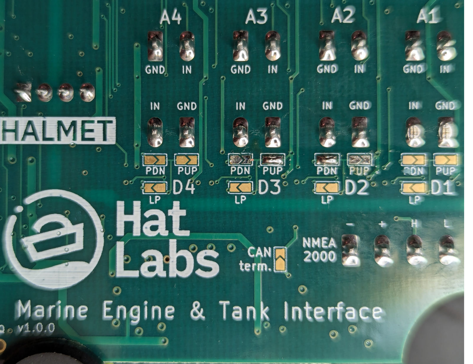
Solder jumpers on the back of the board can be closed to enable built-in pull-up or pull-down resistors.
Likewise, if the switch pulls the signal low when closed like in example (c), the internal pull-up may need to be enabled.
Finally, if the alarm switches are normally closed, the treatment is reversed. When the switch opens, the input voltage will be pulled up or down, depending on the circuit. In this case, the internal pull-up or pull-down may need to be enabled.
Software Setup
The HALMET example firmware provides a ConnectAlarmSender() convenience method for configuring and connecting digital inputs. See main.cpp from line 177 onwards. Both active high and active low signals are supported.
Digital Inputs as Counters
HALMET’s digital inputs can also be used as counters. This is useful for example for counting the number of engine revolutions or chain counter pulses.
Hardware Setup
Usually such senders are driven actively in both directions, so no pull-up or pull-down is required. If you are connecting HALMET to a low-impedance output such as an alternator W terminal, it is advisable to add an in-line fuse to protect the wire from short circuits due to chafing or other damage. Other than that, you can connect the sender directly to the digital input.
If the pulse source is very noisy, resulting in spurious RPM reading, a low-pass filter can be enabled by connecting the LP solder jumper on the back of the board. The low-pass filter has a cutoff frequency of about 2.3 kHz which should be suitable for applications such as alternator W terminal inputs.
Software Setup
The HALMET example firmware implements a pulse counter that can be activated on any or all of the digital inputs. See the example configuration in main.cpp from line 214 onwards.
Using Analog Inputs
HALMET has four analog inputs that can be used for either passive voltage measurements or for active resistance measuring. This section describes how to use the inputs in different common use cases.
Hardware Setup
The analog inputs A1-A4 are connected to an ADS1115 analog-to-digital converter. The ADS1115 has a 16-bit resolution and a maximum sampling rate of 860 samples per second. However, HALMET analog inputs incorporate strong low-pass filter with a cutoff frequency of about 160 Hz. This is still more than sufficient for measuring physical sensor outputs such as tank level sensors or engine pressure sensors.
In the figure below, example (a) shows an existing engine panel gauge connected to a resistive sender. Engine panel gauges are often constructed are usually either thermostatic or magnetic. In both cases, the gauge and the sender act as a voltage divider, and the voltage over the sender is proportional to the measured quantity. This voltage can be measured with HALMET’s analog inputs without interfering the original gauge operation. Due to the voltage divider, the voltage might not correlate linearly with the measured quantity, but this can be compensated for in software.

Connecting analog inputs with and without an existing gauge. (a) With an existing gauge, use HALMET in passive voltage measurement mode. (b) When no other device is present, use HALMET in active resistance measurement mode.
Example (b) shows a case without an existing gauge. The sender is connected directly to the HALMET analog input. In this case, HALMET must provide the excitation voltage for the sender. HALMET implements the resistance measurement using a 10 mA constant current source. The 10 mA current creates a voltage difference of 1 volt over a 100 ohm resistance, for a maximum resistance of approximately 300 ohm. The constant current source is enabled by placing a jumper header on the pin pair of the CCS (constant current source) header. See figure below.
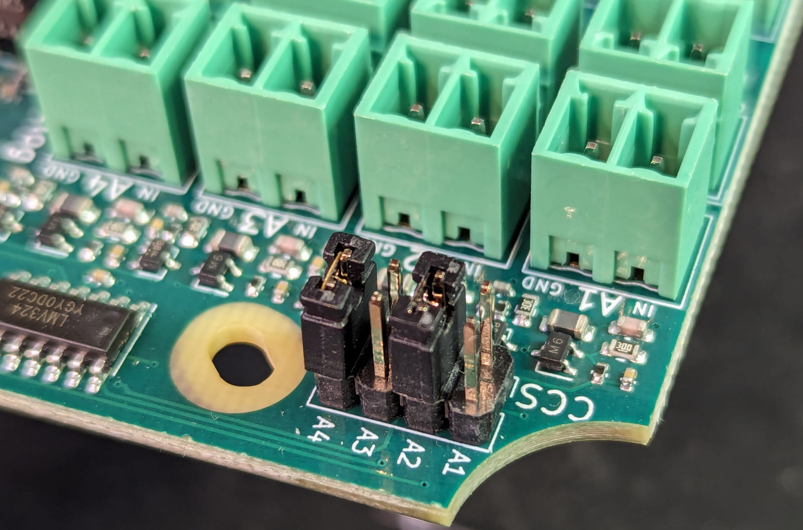
Figure shows the constant current source enabled for analog inputs A2 and A4.
If the panel lights are implemented with LEDs, the voltage drop across the LEDs may not be enough to pull the voltage down to a low enough level. In this case, the pull-down resistor needs to be enabled. ↩︎