ESP32 Introduction
HALMET is based on the powerful ESP32-WROOM-32E microcontroller module. The ESP32 is a dual-core microcontroller with built-in WiFi and Bluetooth connectivity. The ESP32 is a popular choice for IoT applications due to its low cost, good set of peripherals, and ease of use.
Board Functional Blocks
Different functional blocks of the board are described below.
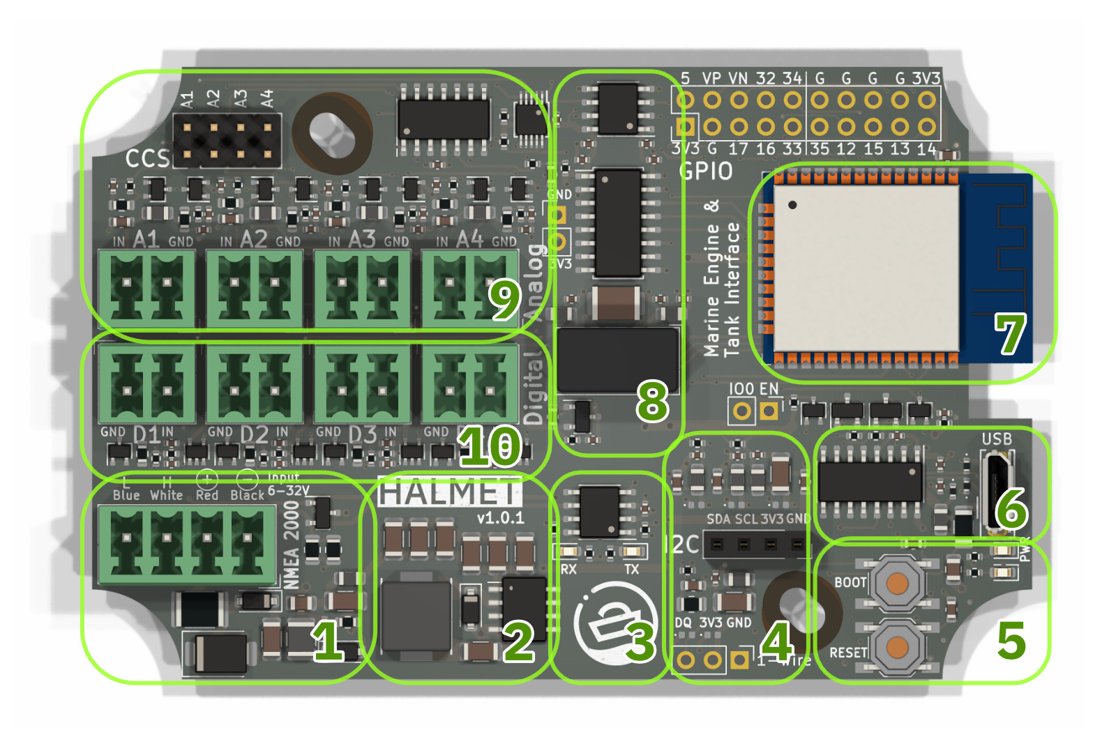
Functional blocks of the HALMET.
NMEA 2000 and power input and protection. The NMEA 2000 connector has the following protection elements:
- 500 mA self-resetting fuse
- Reverse polarity protection diode
- Overvoltage and ESD protection TVS diodes
- Two-stage noise filtering
Power supply. A switching power supply with a maximum output current of 2 A.
CAN transceiver for NMEA 2000. RX and TX LEDs are included to provide a visual indication of CAN bus activity.
I2C and 1-Wire interfaces for connecting additional sensors.
User interface. A reset button, a boot-mode/general-purpose button, a red power LED, and a blue user-programmable LED.
USB 2.0 interface for programming and debugging.
ESP32-WROOM-32E module with built-in WiFi and Bluetooth. The module on the HALMET board includes 16 MB of flash memory.
Galvanic isolation circuitry for the digital and analog inputs.
Analog inputs. The board has four analog inputs with a 16-bit resolution and a maximum input voltage of 33 V. Each input has an under-voltage and over-voltage protection and low-pass filtering with a cutoff frequency at 160 Hz to reduce measurement noise.
The analog inputs have an optional 10 mA constant-current source for active resistance measurement.The constant-current source can be enabled using the CCS jumper headers.
In resistance measurement mode, the maximum resistance that can be measured is 320 ohms.
Digital inputs. HALMET has four digital inputs with a maximum input voltage of +/- 30 V. The inputs feature a Schmitt trigger to improve noise immunity.
Galvanic Isolation
The board has galvanic isolation between the digital and analog inputs and the ESP32 microcontroller. The isolation is achieved using digital isolators for I2C and the four digital inputs, respectively, and an isolated DC/DC converter for powering the isolated section.
Due to the provided isolation, the board can be powered from the NMEA 2000 network without the risk of ground loops. The isolation also provides protection against voltage spikes and noise on the inputs.
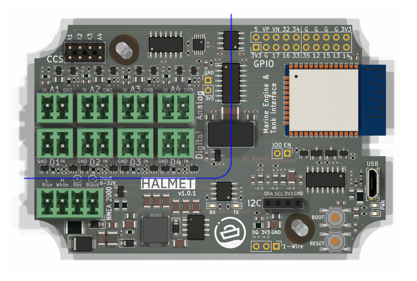
HALMET isolation barrier. The input connectors are isolated from the rest of the board, meaning that they do not share a common ground with the rest of the board.
Connectors
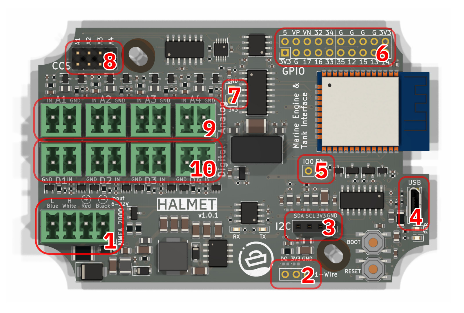
HALMET connectors, top side.
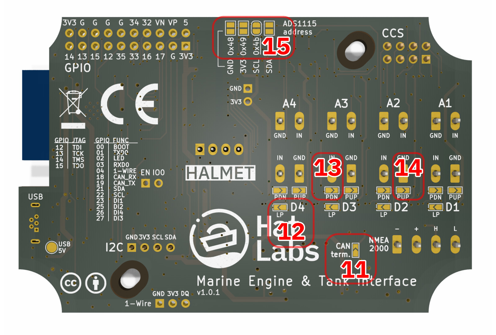
HALMET connectors, bottom side.
Top Side Connectors
NMEA 2000 connector. The connector is a 4-pin Phoenix MC 3.81 compatible pluggable terminal block. The connector is used for connecting the board to a NMEA 2000 network and for powering the board.
1-Wire header connector. The 1-Wire header can be used to connect 1-Wire sensors to the board. The connector is a 3-pin 2.54 mm pitch header. The header is not installed on the board by default because it can interfere with enclosure panel connector placement.
I2C header connector. The I2C header can be used to connect I2C sensors to the board. The connector is a 4-pin 2.54 mm pitch header.
Micro USB connector. The connector is used for programming and debugging the board.
Unpopulated pads for the reset (EN) and boot (IO0) signals.
GPIO header. The GPIO header is a 2x10 pin 2.54 mm pitch header. The header breaks out available ESP32 GPIO pins and can also be used as a JTAG header.
Isolated area power header. The header can be used to power external devices from the isolated section 3V3 and GND.
Jumper header contacts for the constant-current source (CCS) for the analog inputs. The constant-current source can be enabled by shorting the jumper contacts.
Analog input connectors. The connectors are 2-pin Phoenix MC 3.81 compatible pluggable terminal blocks. The connectors are used for connecting analog sensors to the board.
Digital input connectors. The connectors are 2-pin Phoenix MC 3.81 compatible pluggable terminal blocks. The connectors are used for connecting digital sensors to the board.
Bottom Side Connectors
CAN terminator solder jumper. The jumper can be shorted to enable the 120 ohm termination resistor for the CAN bus. Do not use the termination resistor with NMEA 2000 networks.
Low-pass filter solder jumper. The jumper can be shorted to enable a low-pass filter on the respective analog input. The filter has a cutoff frequency of 2.3 kHz. The filter can be used for example for reducing noise ina tachometer signal.
Pull-down resistor solder jumper. The jumper can be shorted to enable a 100 kohm pull-down resistor on the respective digital input. The pull-down resistor can be used to read a normally open switch which is pulled high when closed.
Pull-up resistor solder jumper. The jumper can be shorted to enable a 100 kohm pull-up resistor on the respective digital input. The pull-up resistor can be used to read a normally closed switch which is pulled low when closed.
ADS1115 I2C address selection solder jumpers. The jumpers can be shorted to select the I2C address of the ADS1115 ADC. The jumpers are used to avoid address conflicts when multiple ADS1115 ADCs are connected to the same I2C bus. The pads can also be used to connect additional I2C devices to the isolated board area.
GPIO Reference
HALMET reserves a number of GPIO pins for the input peripherals. Available GPIO pins are broken out to the 2x10 pin GPIO header. The following table lists the GPIO pins and their functions.
| GPIO | Function | Notes |
|---|---|---|
| 0 | Boot button | Enter bootloader when pulled low |
| 1 | TXD0 | Transmit data to USB |
| 2 | LED | Onboard blue LED |
| 3 | RXD0 | Receive data from USB |
| 4 | 1-Wire DQ | 1-Wire data line |
| 5 | - | Available on the GPIO header |
| 12 | - / TDI | Available on the GPIO header. Optionally: JTAG TDI |
| 13 | - / TCK | Available on the GPIO header. Optionally: JTAG TCK |
| 14 | - / TMS | Available on the GPIO header. Optionally: JTAG TMS |
| 15 | - / TDO | Available on the GPIO header. Optionally: JTAG TDO |
| 16 | - | Available on the GPIO header |
| 17 | - | Available on the GPIO header |
| 18 | CAN RX | Receive from NMEA 2000 |
| 19 | CAN TX | Transmit to NMEA 2000 |
| 21 | I2C SDA | I2C data line. Used for analog input |
| 22 | I2C SCL | I2C clock line. Used for analog inputs |
| 23 | DI1 | Digital Input 1 |
| 25 | DI2 | Digital Input 2 |
| 27 | DI3 | Digital Input 3 |
| 26 | DI4 | Digital Input 4 |
| 32 | - | Available on the GPIO header |
| 33 | - | Available on the GPIO header |
| 34 | - | Available on the GPIO header |
| 35 | - | Available on the GPIO header |
| 36 (VP) | Input only | Available on the GPIO header |
| 39 (VN) | Input only | Available on the GPIO header |
Power Supply
The permitted voltage input range on the board is 5-32 V. Typical current consumption is 90 mA at 12 V with the WiFi module active (corresponds to 1.1 W).
NMEA 2000
NMEA 2000 is a ubiquitous communications standard used for connecting sensor, control, and display devices on boats and ships. It is based on the Controller Area Network (CAN bus) which is a vehicle bus standard designed to allow devices to communicate with each other without a host computer.
The board complies with the NMEA 2000 standard as long as none of the unisolated connectors are connected to other ground-referenced devices. For example, a 1-Wire temperature sensor with a long cable can be used since it does not share a common ground with other devices. However, connecting an I2C analog-to-digital converter to the unisolated I2C connector would break the NMEA 2000 compliance.
TODO: NMEA 2000 GPIO Pinout
Status LEDs
There are two buttons and two LEDs on the HALMET board. The two buttons are labeled Reset and Boot. The Reset button resets the board by pulling the ESP32 Enable pin low. The Boot button is connected to GPIO0 and can be used during device startup to force the module into a download mode. Otherwise it can be used as a regular button input.
The two LEDs are not explicitly labeled. The red LED is lit whenever there is 3.3V power on the board. The blue LED is connected to GPIO2 (the pin commonly used for LED on ESP32 development boards). It can be controlled by user programs to indicate the state of the device.
1-Wire
1-Wire is a device communications bus system designed by Dallas Semiconductor, since acquired by Maxim Integrated Products. Although 1-Wire is a slow-speed protocol, supporting only speeds up to 16.3 kbps, it is very simple to implement and can be used over long distances. It is commonly used for temperature sensors and similar simple sensing devices.
The HALMET 1-Wire implementation features ESD and RF noise filtering as well as low-pass filtering to improve network reliability.
Note that the 1-Wire data pin (labeled “DQ”) is physically mapped to GPIO4, so in your program, use GPIO4 for all 1-Wire data.
I2C
I2C (Inter-Integrated Circuit) is a very popular synchronous serial communication bus commonly used for interfacing with a number of different ICs. It uses two data wires in addition to voltage and ground.
HALMET uses I2C internally for the ADS1115 analog-to-digital converter. The I2C bus is also broken out to a 4-pin header for connecting additional I2C devices.
The I2C bus is connected to GPIO21 (SDA) and GPIO22 (SCL) on the ESP32. These pins are the default I2C pins in the Arduino ESP32 environment, but different from the default pins on the SH-ESP32.