Getting Started
Hardware Assembly
To accommodate more flexible connector placement in small enclosures, HALMET boards are delivered without the 1-Wire or GPIO headers installed. If you plan to use either of these interfaces, you will need to solder the headers to the board.
If you need instructions for soldering header pins on the board, have a look at the SH-ESP32 hardware assembly instructions.
Powering the Board
HALMET is powered through the NMEA 2000 connector. If you are going to connect HALMET to a NMEA 2000 network, you can power the board directly from the network. In that case, connect the NMEA 2000 wires to the 4-pin pluggable terminal connector as shown in the following figure.
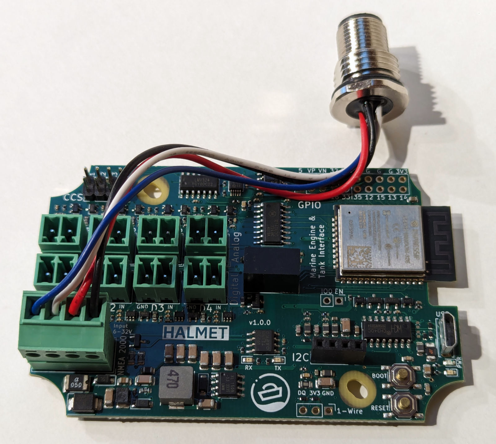
Connect the NMEA 2000 wires to the connector as shown.
If you are not going to connect HALMET to a NMEA 2000 network, use the same connector but only connect wires to the - and + locations. Any 5-32 V power source can be used. Typical current consumption of the board with the WiFi active is 0.07 A at 12 V.
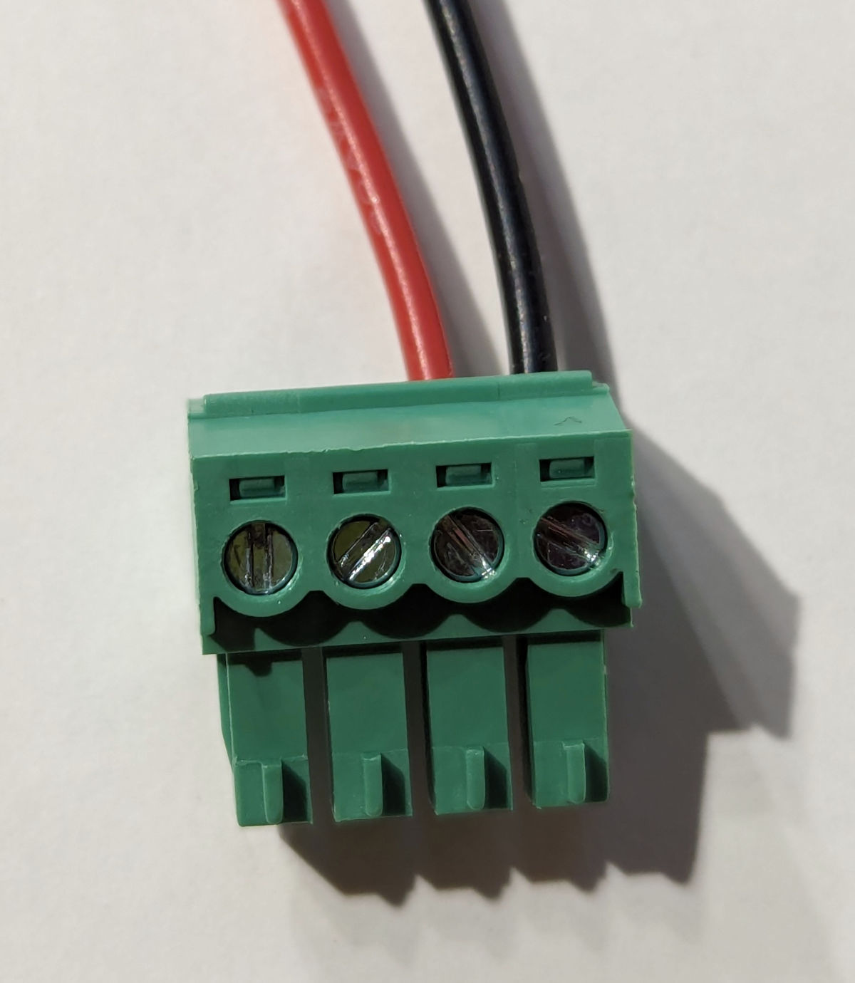
Connect the power wires to the connector as shown.
Enclosures
For use on a boat, HALMET should always be placed in a waterproof enclosure. The board is designed to fit the SH-ESP32 Enclosure. See below for an example of a HALMET board installed in the enclosure.
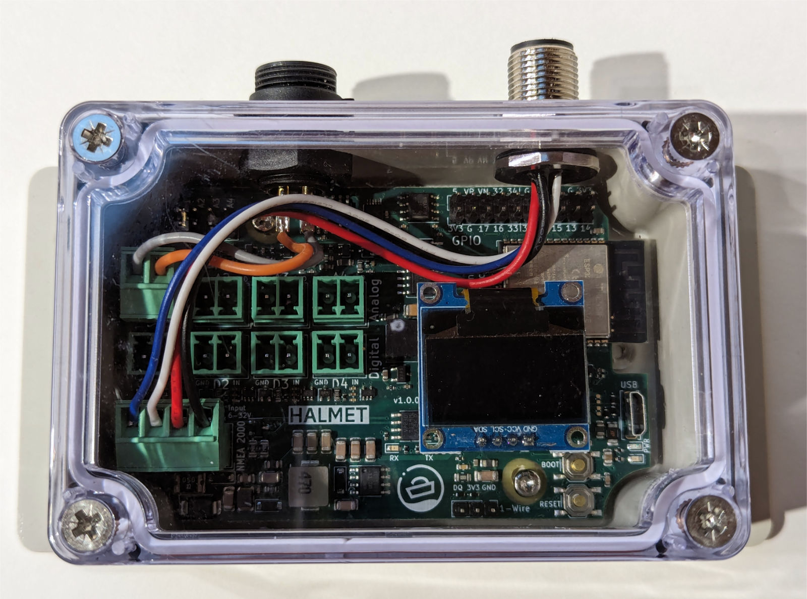
HALMET installed in the SH-ESP32 enclosure.
The SH-ESP32 enclosure has a limited amount of space for connectors. Each of the long sides can practically only take 2-3 panel connectors. If you intend to connect more than a few inputs, a larger enclosure is recommended. For example, the Hat Labs Compact SH-RPi Enclosure, shown below, already has ample room for connectors.
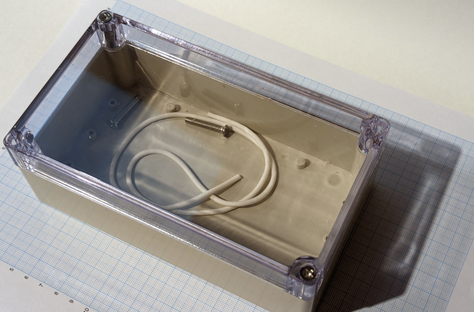
the Compact SH-RPi Enclosure provides more room for panel connector placement.
Other suitable waterproof enclosures can easily be found on any online marketplace. Larger outdoor junction boxes are also suitable for the purpose.
Drilling Holes for Panel Connectors
The enclosures typically do not have pre-drilled holes. When drilling holes, always use a conical or step drill bits (one that looks like a small metal Christmas tree). Standard metal drill bits may easily bite too hard and crack the enclosure wall.
When planning the hole/connector placement, leave sufficient room for tightening the connector nuts and for the connector body. If you’re planning to wall-mount the enclosure, it is recommended to place the connectors facing down to minimize the chances for water ingress.
Suitable hole sizes for different connectors:
- PG7 cable gland and M12 (NMEA 2000) panel connector: 12.5 mm or 1/2"
- SP13 panel connectors (blue-black plastic connectors): 13 mm
- PG9 cable gland: 16 mm or 5/8"
Rubber or silicone grommets allow for significantly higher cable densities than panel connectors or cable glands. However, they are not as waterproof as panel connectors or cable glands. Furthermore, they require permanent cable attachment, which may make servicing the system more difficult.
TODO: Add a picture of a grommet.
Soldering the Panel Connectors
When soldering the internal wires to the panel connectors, always use heat shrink tubing on the individual wires. Always remember to slide the heat shrink onto the wires before soldering… Usually, you can first add solder to the connector pin cavity and then re-melt the solder and insert the wire.