This is the multi-page printable view of this section. Click here to print.
Documentation
1 - Getting Started
Hardware Assembly
To accommodate more flexible connector placement in small enclosures, HALMET boards are delivered without the 1-Wire or GPIO headers installed. If you plan to use either of these interfaces, you will need to solder the headers to the board.
If you need instructions for soldering header pins on the board, have a look at the SH-ESP32 hardware assembly instructions.
Powering the Board
HALMET is powered through the NMEA 2000 connector. If you are going to connect HALMET to a NMEA 2000 network, you can power the board directly from the network. In that case, connect the NMEA 2000 wires to the 4-pin pluggable terminal connector as shown in the following figure.
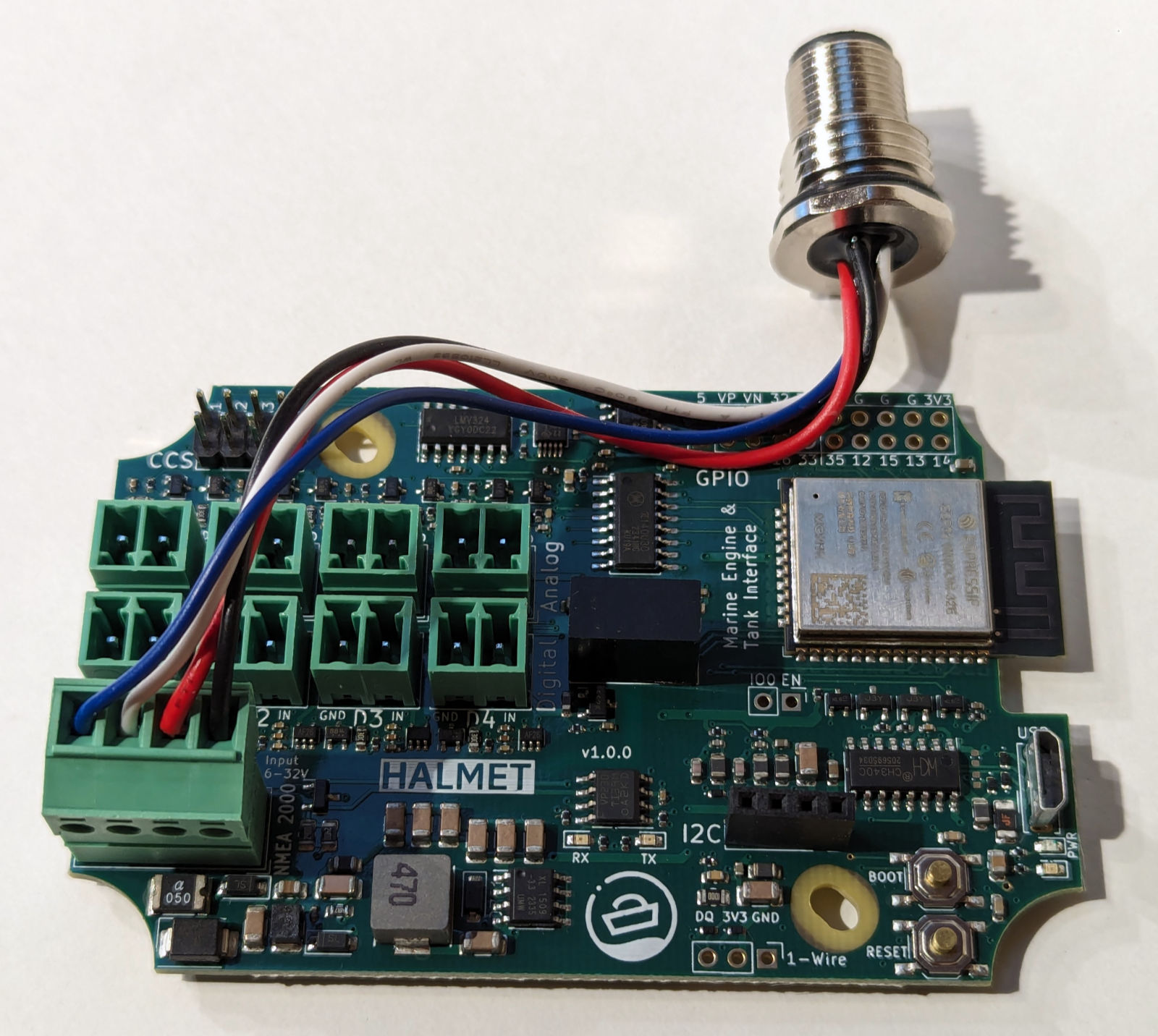
Connect the NMEA 2000 wires to the connector as shown.
If you are not going to connect HALMET to a NMEA 2000 network, use the same connector but only connect wires to the - and + locations. Any 5-32 V power source can be used. Typical current consumption of the board with the WiFi active is 0.07 A at 12 V.
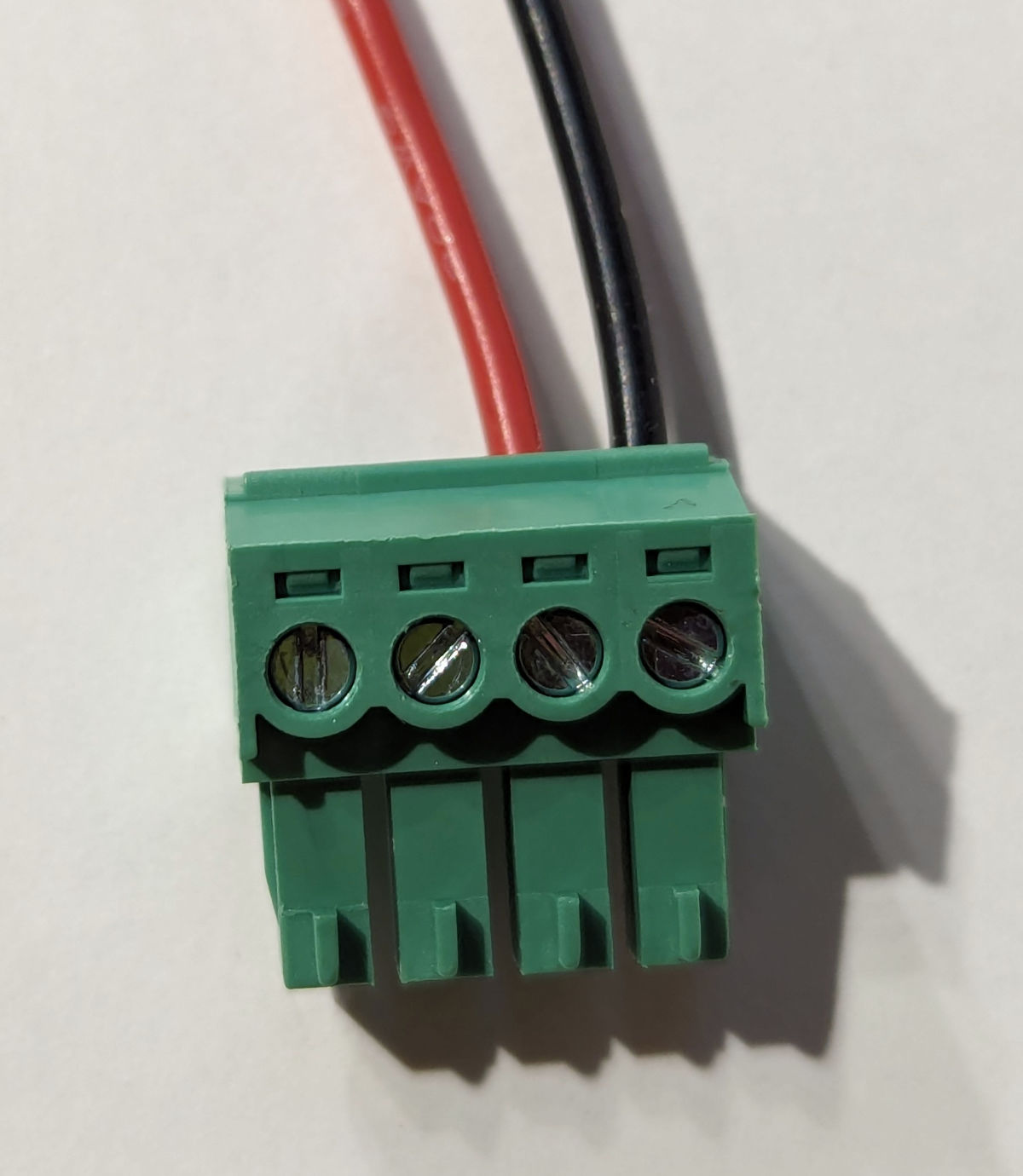
Connect the power wires to the connector as shown.
Enclosures
For use on a boat, HALMET should always be placed in a waterproof enclosure. The board is designed to fit the SH-ESP32 Enclosure. See below for an example of a HALMET board installed in the enclosure.
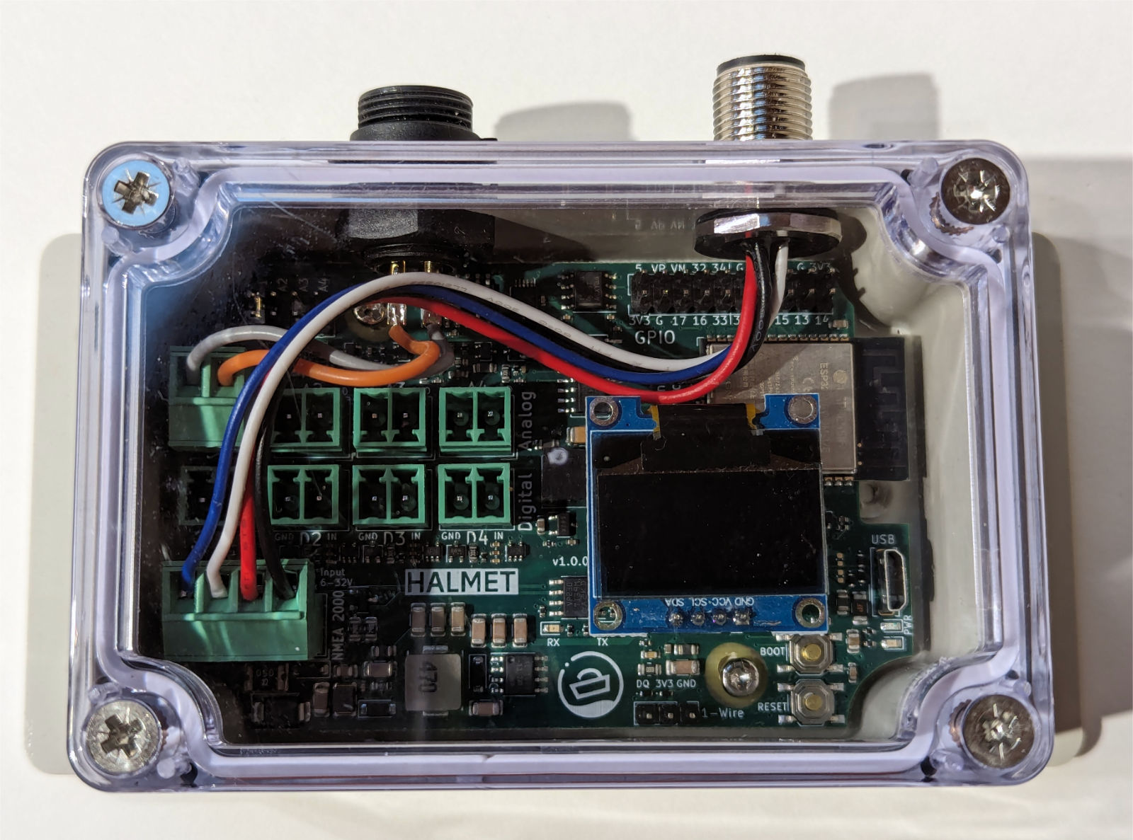
HALMET installed in the SH-ESP32 enclosure.
The SH-ESP32 enclosure has a limited amount of space for connectors. Each of the long sides can practically only take 2-3 panel connectors. If you intend to connect more than a few inputs, a larger enclosure is recommended. For example, the Hat Labs Compact SH-RPi Enclosure, shown below, already has ample room for connectors.
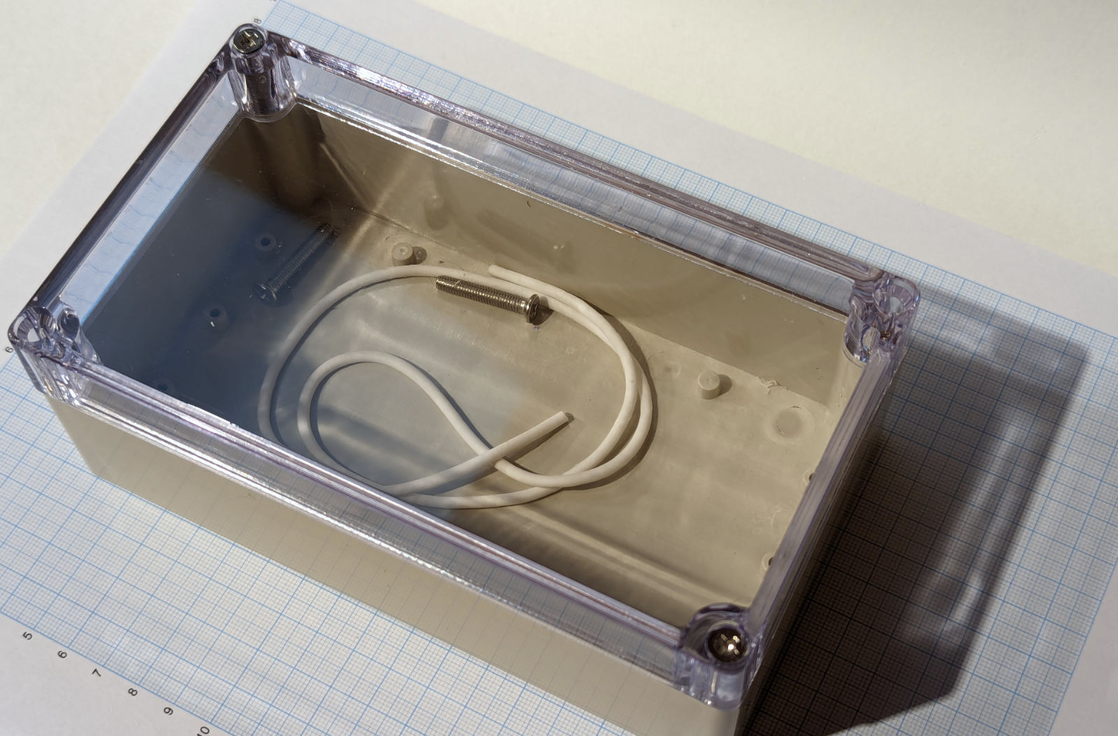
the Compact SH-RPi Enclosure provides more room for panel connector placement.
Other suitable waterproof enclosures can easily be found on any online marketplace. Larger outdoor junction boxes are also suitable for the purpose.
Drilling Holes for Panel Connectors
The enclosures typically do not have pre-drilled holes. When drilling holes, always use a conical or step drill bits (one that looks like a small metal Christmas tree). Standard metal drill bits may easily bite too hard and crack the enclosure wall.
When planning the hole/connector placement, leave sufficient room for tightening the connector nuts and for the connector body. If you’re planning to wall-mount the enclosure, it is recommended to place the connectors facing down to minimize the chances for water ingress.
Suitable hole sizes for different connectors:
- PG7 cable gland and M12 (NMEA 2000) panel connector: 12.5 mm or 1/2"
- SP13 panel connectors (blue-black plastic connectors): 13 mm
- PG9 cable gland: 16 mm or 5/8"
Rubber or silicone grommets allow for significantly higher cable densities than panel connectors or cable glands. However, they are not as waterproof as panel connectors or cable glands. Furthermore, they require permanent cable attachment, which may make servicing the system more difficult.
TODO: Add a picture of a grommet.
Soldering the Panel Connectors
When soldering the internal wires to the panel connectors, always use heat shrink tubing on the individual wires. Always remember to slide the heat shrink onto the wires before soldering… Usually, you can first add solder to the connector pin cavity and then re-melt the solder and insert the wire.
2 - Usage
Common Use Cases
This section contains practical information on reading different types of sensors and connecting HALMET to other devices.
Software Setup
HALMET is a development board and doesn’t come with any software pre-installed. You will need to install suitable software yourself. While this is not difficult, some prior experience with microcontroller boards such as Arduino or ESP32 Devkits is recommended.
HALMET documentation assumes using the HALMET example firmware. This firmware is based on the SensESP framework and provides relatively straightforward access to the board’s features.
SensESP Getting Started Guide provides detailed instructions for installing a development environment required for compiling and installing the firmware. The instructions are written for generic ESP32 devices, but they are also applicable to HALMET. Just use the HALMET example firmware instead of the SensESP project template.
Note that even though the SensESP documentation assumes using Signal K, HALMET is also completely usable as a standalone NMEA 2000 device.
If you prefer not to use SensESP, you can also create your custom firmware with Arduino IDE or ESP-IDF. For many use cases, ESPHome is also a great option.
NOTE: The GPIO pin assignments on HALMET are slightly different from the pin assignments on both the ESP32 Devkit and SH-ESP32. If you are adapting any other software than the HALMET example firmware, you will need to double-check the pin assignments. See the FIXME GPIO Reference for more information.
Using Digital Inputs
HALMET has four digital inputs. These inputs can be used for reading digital alarm signals or as counters. This section describes how to use the inputs in different common use cases. The instructions assume using the HALMET example firmware.
The digital inputs D1-D4 are connected to GPIO pins 23, 25, 27, and 26, respectively. The inputs tolerate voltages between -32V and +32V. The threshold voltage for detecting a high signal is about 1.55 V, with a hysteresis of about 0.7 V.
Connecting to Digital Alarms
This section describes how to connect HALMET to different on/off type signals such as engine or bilge alarms.
Hardware Setup
Typically, different on/off type signals such as engine or bilge alarms can be connected to HALMET’s digital inputs directly. A pull-up or pull-down may be required depending on the signal type.
In the figure below, in example (a), an existing light bulb is present in the circuit. When the switch is open, the light bulb pulls the D1 voltage down. No additional pull-down is required.1 However, in example (b), no other load is present in the circuit. If the switch is open, the D2 voltage will be floating and the input will be randomly either high or low. In this case, the internal pull-down resistor must be enabled by connecting the solder jumper on the back of the board.

Digital inputs in different use cases. (a) Existing light in the circuit. (b) No other load in the circuit, switch pulls the signal high when closed. (c) Switch pulls the signal low when closed.
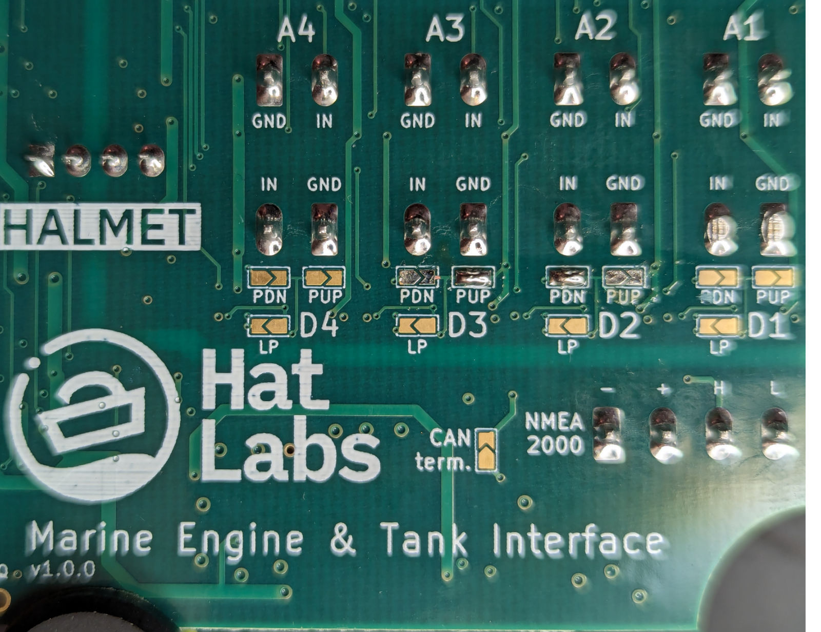
Solder jumpers on the back of the board can be closed to enable built-in pull-up or pull-down resistors.
Likewise, if the switch pulls the signal low when closed like in example (c), the internal pull-up may need to be enabled.
Finally, if the alarm switches are normally closed, the treatment is reversed. When the switch opens, the input voltage will be pulled up or down, depending on the circuit. In this case, the internal pull-up or pull-down may need to be enabled.
Software Setup
The HALMET example firmware provides a ConnectAlarmSender() convenience method for configuring and connecting digital inputs. See main.cpp from line 177 onwards. Both active high and active low signals are supported.
Digital Inputs as Counters
HALMET’s digital inputs can also be used as counters. This is useful for example for counting the number of engine revolutions or chain counter pulses.
Hardware Setup
Usually such senders are driven actively in both directions, so no pull-up or pull-down is required. If you are connecting HALMET to a low-impedance output such as an alternator W terminal, it is advisable to add an in-line fuse to protect the wire from short circuits due to chafing or other damage. Other than that, you can connect the sender directly to the digital input.
If the pulse source is very noisy, resulting in spurious RPM reading, a low-pass filter can be enabled by connecting the LP solder jumper on the back of the board. The low-pass filter has a cutoff frequency of about 2.3 kHz which should be suitable for applications such as alternator W terminal inputs.
Software Setup
The HALMET example firmware implements a pulse counter that can be activated on any or all of the digital inputs. See the example configuration in main.cpp from line 214 onwards.
Using Analog Inputs
HALMET has four analog inputs that can be used for either passive voltage measurements or for active resistance measuring. This section describes how to use the inputs in different common use cases.
Hardware Setup
The analog inputs A1-A4 are connected to an ADS1115 analog-to-digital converter. The ADS1115 has a 16-bit resolution and a maximum sampling rate of 860 samples per second. However, HALMET analog inputs incorporate strong low-pass filter with a cutoff frequency of about 160 Hz. This is still more than sufficient for measuring physical sensor outputs such as tank level sensors or engine pressure sensors.
In the figure below, example (a) shows an existing engine panel gauge connected to a resistive sender. Engine panel gauges are often constructed are usually either thermostatic or magnetic. In both cases, the gauge and the sender act as a voltage divider, and the voltage over the sender is proportional to the measured quantity. This voltage can be measured with HALMET’s analog inputs without interfering the original gauge operation. Due to the voltage divider, the voltage might not correlate linearly with the measured quantity, but this can be compensated for in software.

Connecting analog inputs with and without an existing gauge. (a) With an existing gauge, use HALMET in passive voltage measurement mode. (b) When no other device is present, use HALMET in active resistance measurement mode.
Example (b) shows a case without an existing gauge. The sender is connected directly to the HALMET analog input. In this case, HALMET must provide the excitation voltage for the sender. HALMET implements the resistance measurement using a 10 mA constant current source. The 10 mA current creates a voltage difference of 1 volt over a 100 ohm resistance, for a maximum resistance of approximately 300 ohm. The constant current source is enabled by placing a jumper header on the pin pair of the CCS (constant current source) header. See figure below.
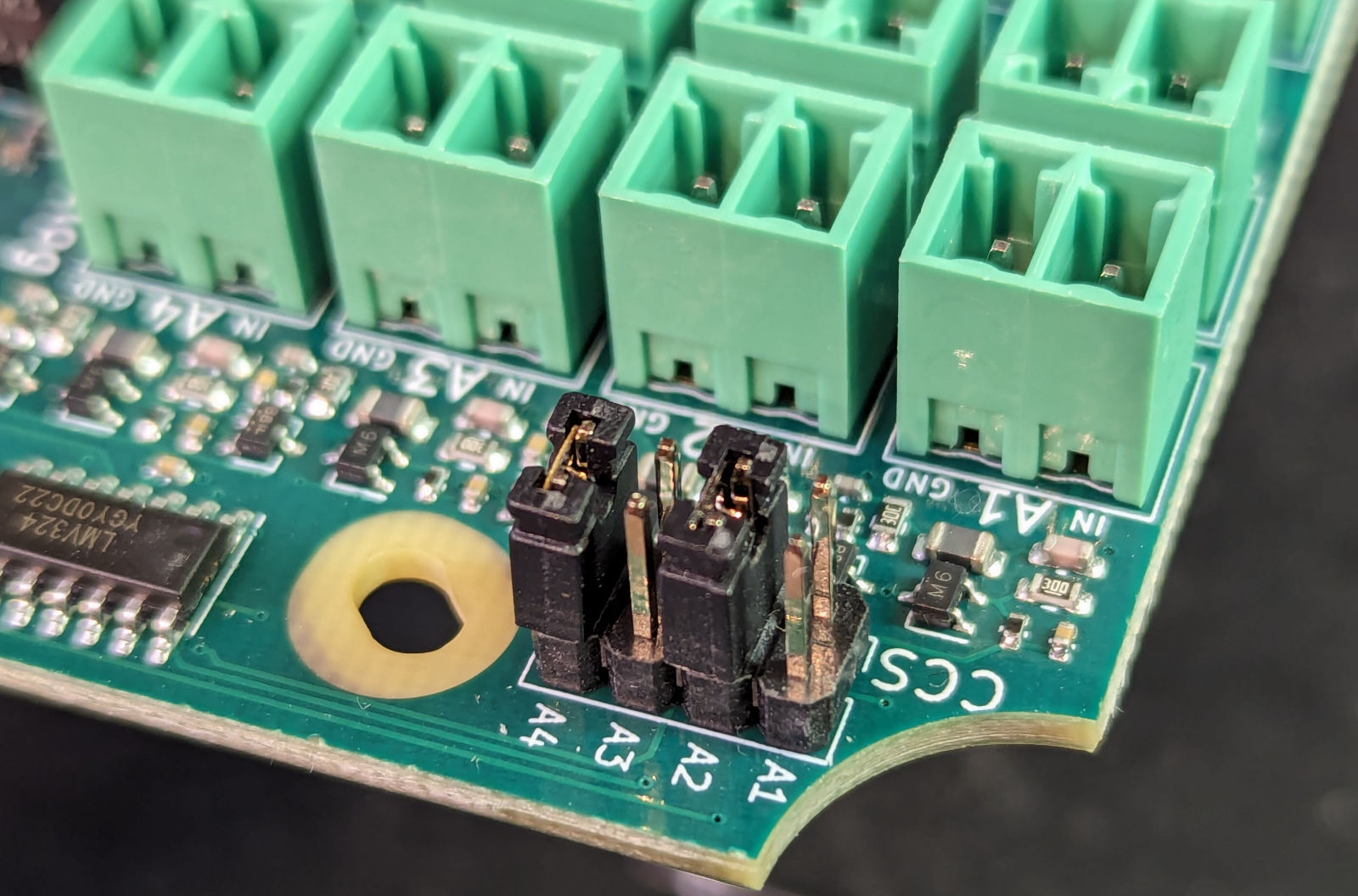
Figure shows the constant current source enabled for analog inputs A2 and A4.
If the panel lights are implemented with LEDs, the voltage drop across the LEDs may not be enough to pull the voltage down to a low enough level. In this case, the pull-down resistor needs to be enabled. ↩︎
3 - Hardware Description
ESP32 Introduction
HALMET is based on the powerful ESP32-WROOM-32E microcontroller module. The ESP32 is a dual-core microcontroller with built-in WiFi and Bluetooth connectivity. The ESP32 is a popular choice for IoT applications due to its low cost, good set of peripherals, and ease of use.
Board Functional Blocks
Different functional blocks of the board are described below.
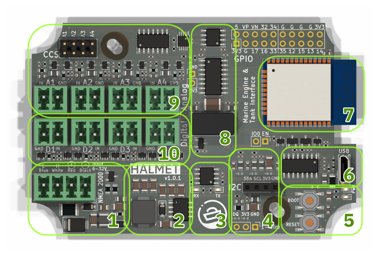
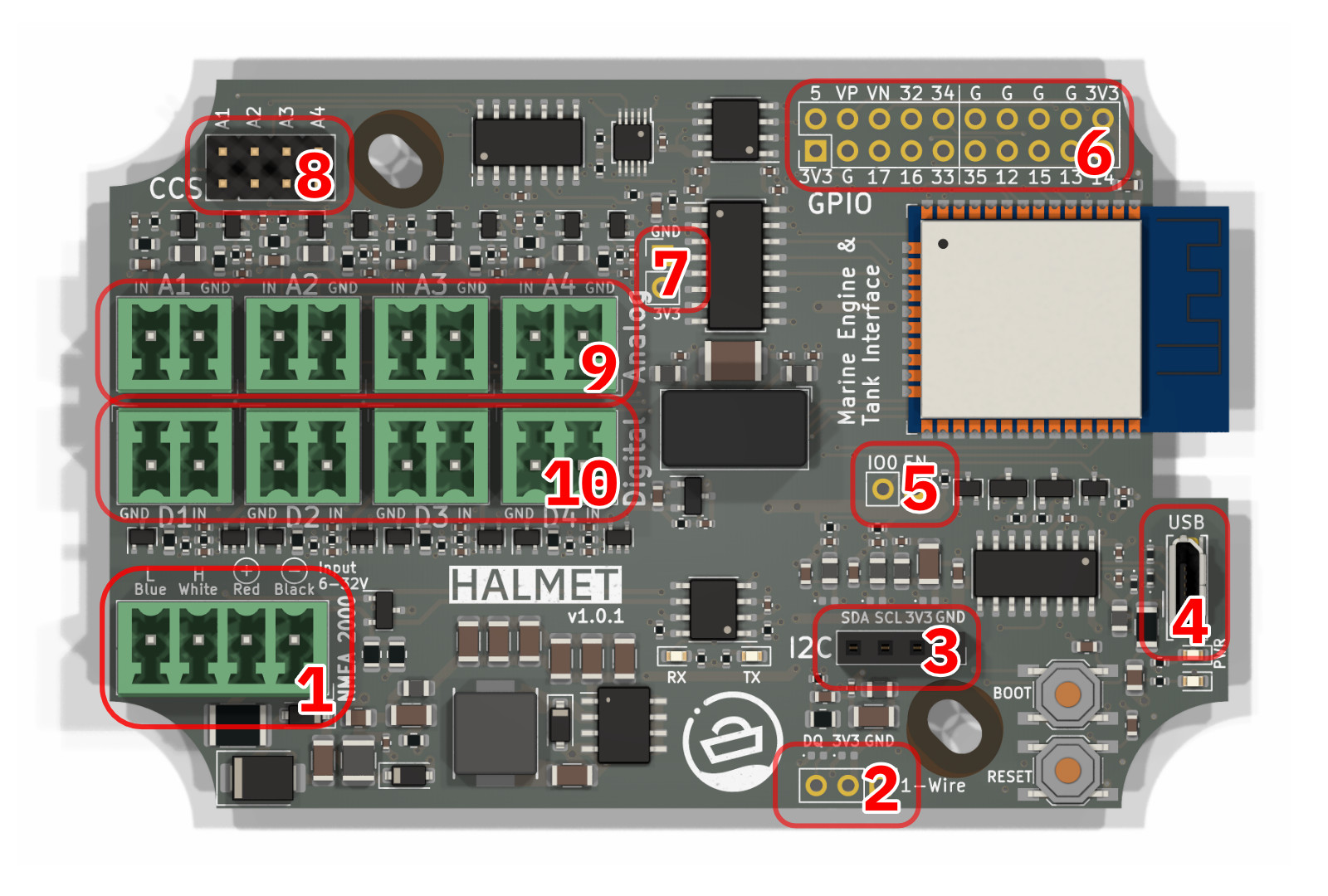
Functional blocks of the HALMET.
NMEA 2000 and power input and protection. The NMEA 2000 connector has the following protection elements:
- 500 mA self-resetting fuse
- Reverse polarity protection diode
- Overvoltage and ESD protection TVS diodes
- Two-stage noise filtering
Power supply. A switching power supply with a maximum output current of 2 A.
CAN transceiver for NMEA 2000. RX and TX LEDs are included to provide a visual indication of CAN bus activity.
I2C and 1-Wire interfaces for connecting additional sensors.
User interface. A reset button, a boot-mode/general-purpose button, a red power LED, and a blue user-programmable LED.
USB 2.0 interface for programming and debugging.
ESP32-WROOM-32E module with built-in WiFi and Bluetooth. The module on the HALMET board includes 16 MB of flash memory.
Galvanic isolation circuitry for the digital and analog inputs.
Analog inputs. The board has four analog inputs with a 16-bit resolution and a maximum input voltage of 33 V. Each input has an under-voltage and over-voltage protection and low-pass filtering with a cutoff frequency at 160 Hz to reduce measurement noise.
The analog inputs have an optional 10 mA constant-current source for active resistance measurement.The constant-current source can be enabled using the CCS jumper headers.
In resistance measurement mode, the maximum resistance that can be measured is 320 ohms.
Digital inputs. HALMET has four digital inputs with a maximum input voltage of +/- 30 V. The inputs feature a Schmitt trigger to improve noise immunity.
Galvanic Isolation
The board has galvanic isolation between the digital and analog inputs and the ESP32 microcontroller. The isolation is achieved using digital isolators for I2C and the four digital inputs, respectively, and an isolated DC/DC converter for powering the isolated section.
Due to the provided isolation, the board can be powered from the NMEA 2000 network without the risk of ground loops. The isolation also provides protection against voltage spikes and noise on the inputs.
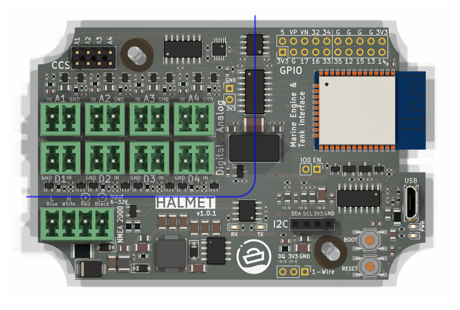
HALMET isolation barrier. The input connectors are isolated from the rest of the board, meaning that they do not share a common ground with the rest of the board.
Connectors
SH-RPi connectors, top side.
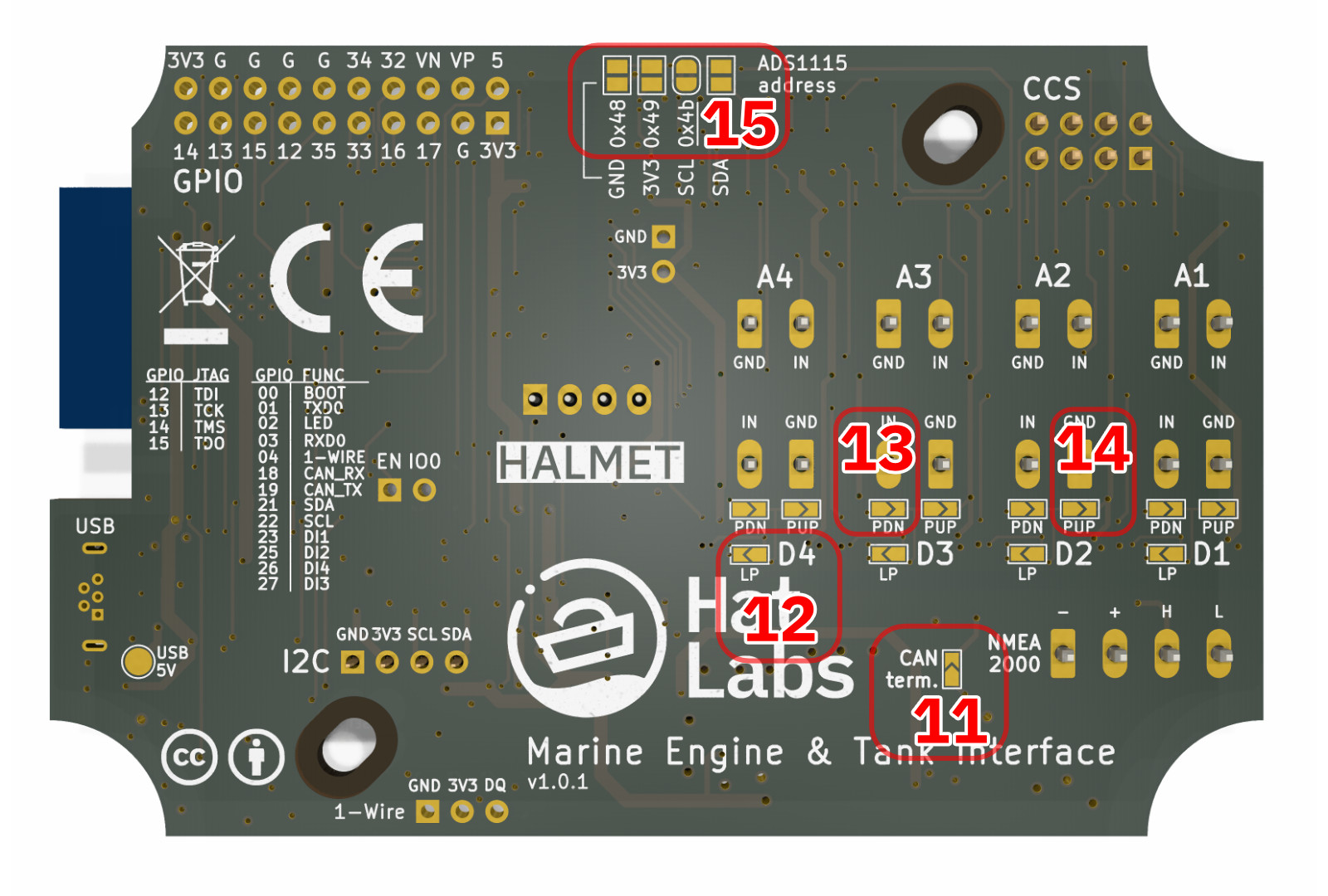
SH-RPi connectors, bottom side.
Top Side Connectors
NMEA 2000 connector. The connector is a 4-pin Phoenix MC 3.81 compatible pluggable terminal block. The connector is used for connecting the board to a NMEA 2000 network and for powering the board.
1-Wire header connector. The 1-Wire header can be used to connect 1-Wire sensors to the board. The connector is a 3-pin 2.54 mm pitch header. The header is not installed on the board by default because it can interfere with enclosure panel connector placement.
I2C header connector. The I2C header can be used to connect I2C sensors to the board. The connector is a 4-pin 2.54 mm pitch header.
Micro USB connector. The connector is used for programming and debugging the board.
Unpopulated pads for the reset (EN) and boot (IO0) signals.
GPIO header. The GPIO header is a 2x10 pin 2.54 mm pitch header. The header breaks out available ESP32 GPIO pins and can also be used as a JTAG header.
Isolated area power header. The header can be used to power external devices from the isolated section 3V3 and GND.
Jumper header contacts for the constant-current source (CCS) for the analog inputs. The constant-current source can be enabled by shorting the jumper contacts.
Analog input connectors. The connectors are 2-pin Phoenix MC 3.81 compatible pluggable terminal blocks. The connectors are used for connecting analog sensors to the board.
Digital input connectors. The connectors are 2-pin Phoenix MC 3.81 compatible pluggable terminal blocks. The connectors are used for connecting digital sensors to the board.
Bottom Side Connectors
CAN terminator solder jumper. The jumper can be shorted to enable the 120 ohm termination resistor for the CAN bus. Do not use the termination resistor with NMEA 2000 networks.
Low-pass filter solder jumper. The jumper can be shorted to enable a low-pass filter on the respective analog input. The filter has a cutoff frequency of 2.3 kHz. The filter can be used for example for reducing noise ina tachometer signal.
Pull-down resistor solder jumper. The jumper can be shorted to enable a 100 kohm pull-down resistor on the respective digital input. The pull-down resistor can be used to read a normally open switch which is pulled high when closed.
Pull-up resistor solder jumper. The jumper can be shorted to enable a 100 kohm pull-up resistor on the respective digital input. The pull-up resistor can be used to read a normally closed switch which is pulled low when closed.
ADS1115 I2C address selection solder jumpers. The jumpers can be shorted to select the I2C address of the ADS1115 ADC. The jumpers are used to avoid address conflicts when multiple ADS1115 ADCs are connected to the same I2C bus. The pads can also be used to connect additional I2C devices to the isolated board area.
GPIO Reference
HALMET reserves a number of GPIO pins for the input peripherals. Available GPIO pins are broken out to the 2x10 pin GPIO header. The following table lists the GPIO pins and their functions.
| GPIO | Function | Notes |
|---|---|---|
| 0 | Boot button | Enter bootloader when pulled low |
| 1 | TXD0 | Transmit data to USB |
| 2 | LED | Onboard red LED |
| 3 | RXD0 | Receive data from USB |
| 4 | 1-Wire DQ | 1-Wire data line |
| 5 | - | Available on the GPIO header |
| 12 | - / TDI | Available on the GPIO header. Optionally: JTAG TDI |
| 13 | - / TCK | Available on the GPIO header. Optionally: JTAG TCK |
| 14 | - / TMS | Available on the GPIO header. Optionally: JTAG TMS |
| 15 | - / TDO | Available on the GPIO header. Optionally: JTAG TDO |
| 16 | - | Available on the GPIO header |
| 17 | - | Available on the GPIO header |
| 18 | CAN RX | Receive from NMEA 2000 |
| 19 | CAN TX | Transmit to NMEA 2000 |
| 21 | I2C SDA | I2C data line. Used for analog input |
| 22 | I2C SCL | I2C clock line. Used for analog inputs |
| 23 | DI1 | Digital Input 1 |
| 25 | DI2 | Digital Input 2 |
| 27 | DI3 | Digital Input 3 |
| 26 | DI4 | Digital Input 4 |
| 32 | - | Available on the GPIO header |
| 33 | - | Available on the GPIO header |
| 34 | - | Available on the GPIO header |
| 35 | - | Available on the GPIO header |
| 36 (VP) | Input only | Available on the GPIO header |
| 39 (VN) | Input only | Available on the GPIO header |
Power Supply
The permitted voltage input range on the board is 5-32 V. Typical current consumption is 90 mA at 12 V with the WiFi module active (corresponds to 1.1 W).
NMEA 2000
NMEA 2000 is a ubiquitous communications standard used for connecting sensor, control, and display devices on boats and ships. It is based on the Controller Area Network (CAN bus) which is a vehicle bus standard designed to allow devices to communicate with each other without a host computer.
The board complies with the NMEA 2000 standard as long as none of the unisolated connectors are connected to other ground-referenced devices. For example, a 1-Wire temperature sensor with a long cable can be used since it does not share a common ground with other devices. However, connecting an I2C analog-to-digital converter to the unisolated I2C connector would break the NMEA 2000 compliance.
TODO: NMEA 2000 GPIO Pinout
Status LEDs
There are two buttons and two LEDs on the HALMET board. The two buttons are labeled Reset and Boot. The Reset button resets the board by pulling the ESP32 Enable pin low. The Boot button is connected to GPIO0 and can be used during device startup to force the module into a download mode. Otherwise it can be used as a regular button input.
The two LEDs are not explicitly labeled. The red LED is lit whenever there is 3.3V power on the board. The blue LED is connected to GPIO2 (the pin commonly used for LED on ESP32 development boards). It can be controlled by user programs to indicate the state of the device.
1-Wire
1-Wire is a device communications bus system designed by Dallas Semiconductor, since acquired by Maxim Integrated Products. Although 1-Wire is a slow-speed protocol, supporting only speeds up to 16.3 kbps, it is very simple to implement and can be used over long distances. It is commonly used for temperature sensors and similar simple sensing devices.
The HALMET 1-Wire implementation features ESD and RF noise filtering as well as low-pass filtering to improve network reliability.
Note that the 1-Wire data pin (labeled “DQ”) is physically mapped to GPIO4, so in your program, use GPIO4 for all 1-Wire data.
I2C
I2C (Inter-Integrated Circuit) is a very popular synchronous serial communication bus commonly used for interfacing with a number of different ICs. It uses two data wires in addition to voltage and ground.
HALMET uses I2C internally for the ADS1115 analog-to-digital converter. The I2C bus is also broken out to a 4-pin header for connecting additional I2C devices.
The I2C bus is connected to GPIO21 (SDA) and GPIO22 (SCL) on the ESP32. These pins are the default I2C pins in the Arduino ESP32 environment, but different from the default pins on the SH-ESP32.
4 - Software
Introduction
As a developer board, HALMET arrives with no pre-installed software. You will need to install suitable software yourself. While this is not difficult, some prior experience with microcontroller boards such as Arduino or ESP32 Devkits is recommended.
Example firmware for HALMET is available at the HALMET-example-firmware GitHub repository.
Please note that support for software development issues are only provided through the Hat Labs discussion forum.
Further instructions to come soon.
5 - Tutorials and Example Projects
HALMET tutorials and example projects will be listed on this page.
6 - Hardware revisions
Introduction
This page documents different board revisions and provides links to the schematics. Full design file history is available at the HALMET-hardware GitHub repository.
Version 1.0.0
First published version.
Schematics: HALMET-v1.0.0-schema.pdf
7 - Errata
This page lists all known hardware bugs for different HALMET revisions.
Version 1.0.0
Digital inputs 3 and 4 are swapped on the back side silk screen. The correct pinout is:
- DI3: GPIO 27
- DI4: GPIO 26