Instructions for different add-on hardware will be provided on this page.
This is the multi-page printable view of this section. Click here to print.
Add-on hardware
- 1: Compute Module 4
- 2: Waveshare 2-Channel Isolated CAN HAT
- 3: Waveshare 2-Channel Isolated RS485 HAT
- 4: Waveshare MAX-M8Q GNSS HAT
1 - Compute Module 4
The Compute Module 4 is a small form factor computer module that plugs into a carrier board. Providing CPU performance identical to the Raspberry Pi 4B,tThe CM4 is a powerful, flexible, and low-cost solution for embedded applications. When building embedded computers, the CM4 has several advantages over the Raspberry Pi 4B:
- Built-in eMMC flash memory: The CM4 boards have, depending on the model, up to 32 GB of eMMC flash memory. This memory is both more reliable and faster than the SD card used in the Raspberry Pi 4B.
- Option for an external WiFi antenna: The CM4 has a dedicated connector for an external WiFi antenna. This is useful if the signal strength of the internal WiFi antenna is not sufficient.
- M.2 connector: Many base boards have an M.2 connector that can be used to connect an M.2 SSD or an M.2 WiFi module.
- Lower power consumption: in informal testing, we have found a CM4 and a base board to consume over 20% less power than a Raspberry Pi 4B.
On the downside, most of the CM4 base boards do not include an USB 3.0 hub, meaning that the USB ports are limited to USB 2.0 speeds. Also, flashing the eMMC is slightly more complicated than flashing an SD card. The process is described below.
Flashing the eMMC Memory on the CM4
First, you need to download a suitable image. We are using the OpenPlotter Headless image as an example, but the process is the same for other images. Note: Always use a 64-bit image! Some software components will have issues when running on a 32-bit system (InfluxDB, in particular).
The eMMC memory can be flashed with the same image as the Raspberry Pi 4B. The flashing process has two extra steps. First, the CM4 needs to be switched into a special BOOT mode which actually prevents the device from booting and allows flashing the eMMC. Second, on the computer used for flashing, a small rpiboot utility needs to be installed and run to allow mounting the eMMC memory on your computer. Once these steps are completed, the flashing process is identical to the one used for the Raspberry Pi 4B.
For Windows, the rpiboot is available as a pre-compiled executable, but for Linux and MacOS, you need to compile it from source. The process for each platform is described in the chapters below.
Notes on the installation process:
- To flash the eMMC, the base board needs to be switched to BOOT mode. On the Waveshare CM4-IO-BASE boards, the small BOOT switch next to the HDMI0 connector needs to be turned to the ON position.
- The base board needs to be connected to an external power source during the flashing process. Use the SH-RPi board for this purpose!
Windows
- To set up the flashing mode on the host computer, follow the instructions provided in the Raspberry Pi documentation.
- Follow the installation instructions for OpenPlotter.
- Note: Do not boot the system yet! We need to adjust a few settings first, as described in the CM4 Configuration section below.
- After changing the configuration settings, switch the BOOT switch back to OFF position and reboot the system. You can then continue with the OpenPlotter instructions.
Mac
On a Mac, you need to compile the rpiboot utility from source.
- To compile the utility, you need to have Homebrew installed. Do that first.
- Then, follow the steps given in the
usbbootrepository. When you run thesudo ./rpiboot, you should have the CM4 base board connected to your computer and powered up using the SH-RPi. If you get an error message, check the USB cable and the BOOT switch on the base board. - Follow the installation instructions for OpenPlotter. Note: Do not boot the system yet! We need to adjust a few settings first, as described in the CM4 Configuration section below.
- After changing the configuration settings, switch the BOOT switch back to OFF position and reboot the system. You can then continue with the OpenPlotter instructions.
Linux
Like on a Mac, you need to compile the rpiboot utility from source on Linux.
- To compile the utility, you need to have Homebrew installed. Do that first.
- Then, follow the steps given in the
usbbootrepository. When you run thesudo ./rpiboot, you should have the CM4 base board connected to your computer and powered up using the SH-RPi. If you get an error message, check the USB cable and the BOOT switch on the base board. - Follow the installation instructions for OpenPlotter. Note: Do not boot the system yet! We need to adjust a few settings first, as described in the CM4 Configuration section below.
- After changing the configuration settings, switch the BOOT switch back to OFF position and reboot the system. You can then continue with the OpenPlotter instructions.
CM4 Configuration
Enabling USB Ports
Before you boot the system for the first time, you need to make a few changes to the configuration. By default, the USB ports are disabled on the CM4. Obviously, this can be a major issue if you want to use the system with a keyboard and mouse. To enable the USB ports, you need to edit the config.txt file on the eMMC memory. The Boot partition should already be mounted on your computer as a USB drive. Open the drive and edit the config.txt file. Add the following line to the end of the file:
dtoverlay=dwc2,dr_mode=host
Save the file and close it.
Enable External WiFi Antenna
If you have an external WiFi antenna, you need to edit the config.txt file again. Add the following line to the end of the file:
dtparam=ant2
Other possible values are ant1 for the PCB antenna and noant for disabling both antennas. The default value is ant1.
2 - Waveshare 2-Channel Isolated CAN HAT
The Waveshare 2-Channel Isolated CAN HAT provides two isolated CAN interfaces for the Raspberry Pi. The CAN HAT is based on the MCP2515 CAN controller and SI65HVD230/SN65HVD230 CAN transceivers. The HAT can be used to implement a single compliant NMEA 2000 interface or two other CAN interfaces. When used as an NMEA 2000 interface, the second channel should be unused due to NMEA 2000 isolation requirements.
The HAT has an integrated isolated DC/DC transformer and doesn’t require external power input.
This page describes the installation and configuration of the CAN HAT when used together with the Sailor Hat for Raspberry Pi. For further details on the CAN HAT, see the Waveshare wiki page.
Jumper Configuration
Warning
Verify the jumper positions before connecting the HAT!The CAN HAT has two jumpers for onboard CAN bus termination resistors. For normal operation, they must be set to the OFF position!
Additionally, the CAN HAT has a voltage selection jumper. It must be set to 3V3 when using with a Raspberry Pi, otherwise damage to the Raspberry Pi may occur.
Connecting the HAT
Carefully insert the stack-through header into the CAN HAT GPIO connector. Then, plug the HAT onto the Raspberry Pi’s or the Sailor Hat’s 40-pin GPIO header. The connector edge should be secured to the board below with the hex standoffs.
When using the HAT with an NMEA 2000 interface, only the CAN0 interface should be used. The CAN1 interface should be left unconnected. The figure below shows the wiring for the NMEA 2000 interface.
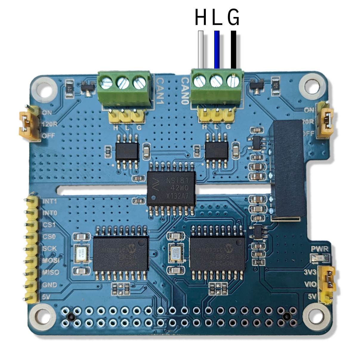
Wiring for the NMEA 2000 interface. The red wire is left unconnected.
Software Configuration
The Sailor Hat installation script can be used to configure and enable the CAN interface. If you want do perform a manual installation, see the Waveshare wiki page for details.
Powering the SH-RPi using the NMEA 2000 Interface
It is possible to power the Raspberry Pi using the NMEA 2000 interface. For this, the NMEA 2000 power and ground wirens should be connected to the SH-RPi power input, while the H and L wires should go to the CAN0 header on the CAN HAT. Additionally, a ground connection should be made between the SH-RPi and the CAN HAT as shown in the figure below.
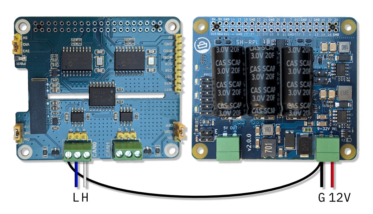
Wiring configuration for powering the SH-RPi using the NMEA 2000 interface.
3 - Waveshare 2-Channel Isolated RS485 HAT
The Waveshare 2-Channel Isolated RS485 HAT provides two isolated RS-485 interfaces for the Raspberry Pi. It can be used to implement a bidirectional NMEA 0183 interface or two generic bidirectional RS-485 interfaces. When used as an NMEA 0183 interface, one channel is used for receiving and the other for transmitting data.
The HAT has an integrated isolated DC/DC transformer and doesn’t require external power input.
The RS485 HAT can be used simultaneously with the SH-RPi and the CAN HAT.
This page describes the installation and configuration of the RS485 HAT when used together with the Sailor Hat for Raspberry Pi. For further details on the RS485 HAT, see the Waveshare wiki page.
Jumper Configuration
Warning
Verify the jumper positions before connecting the HAT!The RS485 HAT has two jumpers for onboard RS-485 bus termination resistors. NMEA 0183 does not use terminators, and the jumpers must be set to the OFF position!
Connecting the HAT
Carefully insert the stack-through header into the RS-485 HAT GPIO connector. Then, plug the HAT onto the Raspberry Pi’s or the Sailor Hat’s 40-pin GPIO header. The connector edge should be secured to the board below with the hex standoffs.
When using the HAT as an NMEA 0183 interface, Channel 1 is used for receiving data (RX) and Channel 2 for transmitting data (TX). The transmitting device TX A and B wires (or TX+ and TX-) should be connected to the HAT Channel 1 A and B terminals, while the receiving device RX A and B wires (or RX+ and RX-) should be connected to the HAT Channel 2 A and B terminals. The figure below shows the wiring for the NMEA 0183 interface.
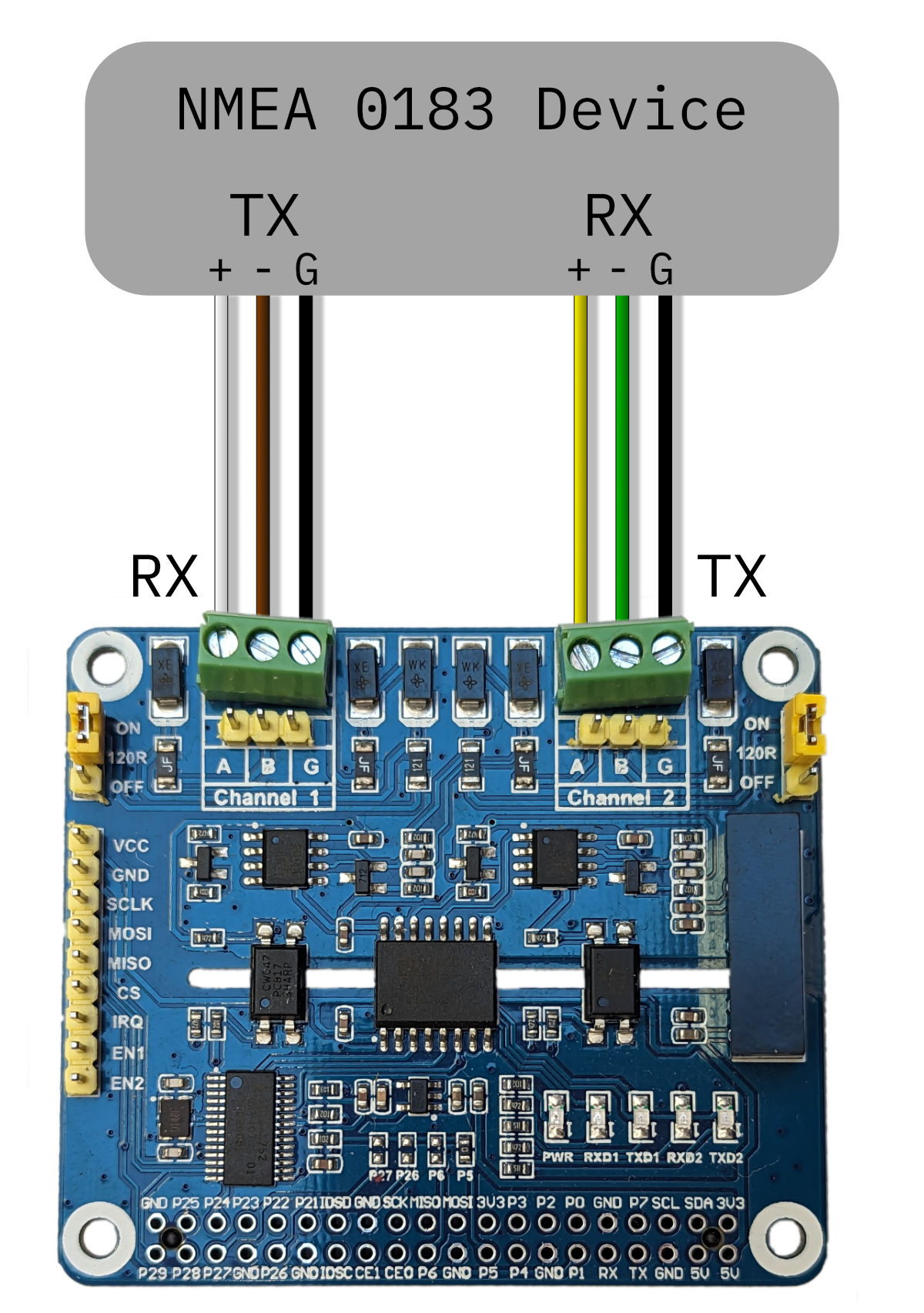
Wiring for the NMEA 0183 interface. The wiring colors may vary depending on the device.
Software Configuration
The Sailor Hat installation script can be used to configure and enable the RS-485 interface. The interface will be provided by two serial devices: /dev/ttySC0 and /dev/ttySC1. Of these, /dev/ttySC0 is used for receiving data and /dev/ttySC1 for transmitting data. These can be configured in the Signal K data connections or any other NMEA 0183 application of your choice.
If you want do perform a manual installation, see the Waveshare wiki page for details.
4 - Waveshare MAX-M8Q GNSS HAT
The Waveshare MAX-M8Q GNSS HAT provides a high-quality GNSS receiver for the Raspberry Pi, based on the U-blox MAX-M8Q module. MAX-M8Q features a multi-constellation GNSS receiver with a high sensitivity of -167 dBm. It supports GPS, GLONASS, BeiDou and Galileo and can receive concurrently from three of these. Additionally, several augmentation schemes such as SBAS, QZSS, IMES and D-GPS are supported.
This page describes the installation and configuration of the GNSS HAT when used together with the Sailor Hat for Raspberry Pi. For further details on the GNSS HAT, see the Waveshare wiki page.
Connecting the HAT
Insert the stack-through header into the GNSS HAT GPIO connector. Then, plug the HAT onto the Raspberry Pi’s 40-pin GPIO header. The GNSS HAT can be stacked on top of other hats.
Using the GNSS HAT together with the RS485 HAT
The MAX-M8Q GNSS HAT features a TIMEPULSE (PPS) feature that is used to provide a highly accurate GNSS time reference to the Raspberry Pi. Unfortunately, this time pulse feature is connected to a GPIO pin that is also used by the RS485 HAT. If these two devices are used together, the conflicting GPIO pin must be physically disconnected. The easiest way to do this is to cut the respective pin on the stack-through header. The figure below highlights the pin that needs to be cut.
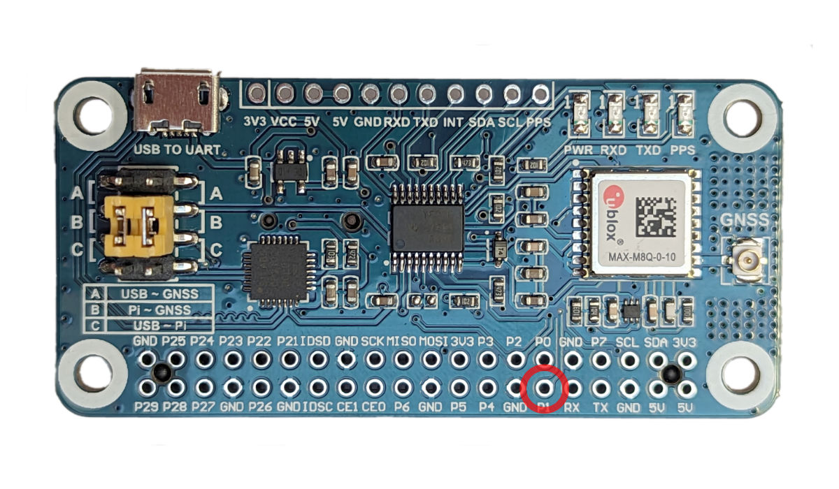
The pin that needs to be cut when using the GNSS HAT together with the RS485 HAT.
To ensure the correct pin is cut, insert the stack-through header partially onto the GNSS HAT GPIO connector. Then, cut the top of the pin that is highlighted in the figure above. Disconnect the stack-through header and then cut the pin at the base of the connector.
Software Configuration
GNSS HAT software installation will be automated using the Sailor Hat installation script.
As of now, you need to configure the GNSS HAT manually according to the instructions on the Waveshare MAX-M8Q GNSS HAT wiki page. You do not need the steps beyond gpsd configuration.
Depending on the configuration, the GNSS HAT will provide a serial device /dev/ttyAMA0 or /dev/ttyS0 for NMEA 0183 data. OpenPlotter has a nifty serial device configuration utility which can be used to set up and connect the GNSS HAT to Signal K.
Backup Battery
The GNSS HAT features a backup battery connector. The backup battery is used to store ephemeris information in case the Raspberry Pi is powered off. The backup battery is not mandatory but will speed up the time it takes to get a GNSS fix after powering on the Raspberry Pi.
The backup battery type is ML1220. It is a rechargeable Lithium cell and must not be replaced with a non-rechargeable battery. Doing so will result in a risk of explosion and fire! Advanced users can, at their own risk, remove the R3 resistor to disable the charging functionality to use a non-rechargeable CR1220 battery. The schematics and PCB layout are available at the Waveshare wiki page.